
Arduino Crash Course – Project 1
Are you ready for a 0 assisted project? I believe you are if you truly followed along the first 2 lessons of this crash course. After every several lessons or so, I will post a project that will leverage the new found knowledge from the recent lessons. The key point to these projects is not to make you struggle. You should be excited to try and solve on your own.
Before I describe the first project of this crash course, let’s cover some more key topics (don’t worry, these topics won’t be a part of the project, but will most likely come up in future lessons and potentially future projects). As you may already know from the first 2 lessons, or you will quickly find out, this Arduino Crash Course is completely different in that I am trying to not just provide you with how to build or complete a specific project, but provide you with the knowledge to go beyond simple applications found all over the web to be able to produce things on your own.
Series Vs. Parallel Connections
There are 2 different types of connections in electrical circuitry (well 3 if you include the neither series nor parallel case). You have actually already been exposed to Series circuits in previous lessons in this Arduino crash course.
Series Circuit
A series circuit is simply defined that electricity, or current in particular, out of one component has no where to go but into the next component in the circuit. So if we take an example of the photocell resistor (or any of the resistors connected to LEDs) in the previous lessons of this crash course, these resistors are in series with the LEDs. The current has no where to go but from the resistor to the anode of the LED. Earlier in the first lesson we were introduced to Ohm’s Law which is the guiding principle of how Voltage (V, sometimes E) measured in volts, Current (I) measured in Amps, and Resistance (R) measured in Ω where V = IR.
For components connected in series, the current (I) is the same through each component within that series, but there will be a voltage drop across each component based on the resistance of that particular component. Let’s work through a specific example. Say we just had 3 resistors in series connected to a battery (NOTE: do not physically do this unless you know the resistors are able to handle the wattage. Wattage will be discussed in later lessons in this crash course, so if you don’t know, don’t physically try it!).
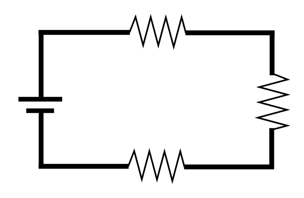
From this description, we can actually calculate how much current if flowing through this circuit by Ohm’s Law. We know the voltage is 9V, and we know the individual resistances of each resistor. One property of Series is the total resistance of the circuit is the sum of all the components resistances. Therefore, we have 220Ω+1000Ω+780Ω = 2000Ω total resistance in this circuit. So finish plugging in the number into Ohm’s Law and we have:
9V = I*2000Ω => I = .0045A or 4.5mA (milliAmps)
So we know the current of the flowing through this circuit. But can we calculate the voltage drop across each resistor? You betcha! And you guessed it, it’s using Ohm’s Law
V_1 = .0045A*220Ω = 0.99V
V_2 = .0045A*1000Ω = 4.5V
V_3 = .0045A*780Ω = 3.51V
Where V_1, V_2, V_3 represents the voltage drop after passing through R1, R2, and R3 respectively. You may have noticed that if you sum up all the voltages, it represents our source voltage of 9V which is another characteristic of series circuits.
Parallel Circuit
A parallel circuit is a circuit where the conductor splits and connects to 2 or more components before rejoining back on the negative side of each component. It may be easier to think of it as a flow of current being split and then rejoined. If we take another resistor example, we have a diagram such as:

A key property of parallel circuits, is the voltage is the same across the parallel circuit, so all resistors will be sourced at 9V (of course assuming 0 resistance in the conductor connecting the resistors). The current through the circuit is the sum of the currents flowing through all resistors (or any loads) connected in parallel. Let’s calculate the current through each resistor knowing that the 9V remains the same across all:
I_1 = 9V / 220Ω ~ 0.04091A
I_2 = 9V / 1000Ω = .009A
I_3 = 9V / 780Ω ~0.01154
So can we calculate the total resistance of these resistors in parallel? You betcha! Although, do note that we did have to round current through 1st and 3rd resistor, so it won’t be match perfectly like the series circuit but it’ll be close:
9V = (0.04091A + .009A + 0.01154A) * R
R = 9V / 0.06145A ~ 146.46054Ω
This brings up another key property for calculating total resistance:
1/R_TOT = 1/R_1 + 1/R_2 + 1/R_3 + …. + 1/R_N
Where R_TOT is the total resistance, and R_1 to R_N is the individual resistances in parallel. If we take the resistors values and use this formula, you should arrive at roughly the same answer for total resistance (again will be slightly off, but that’s do to rounding that was done).
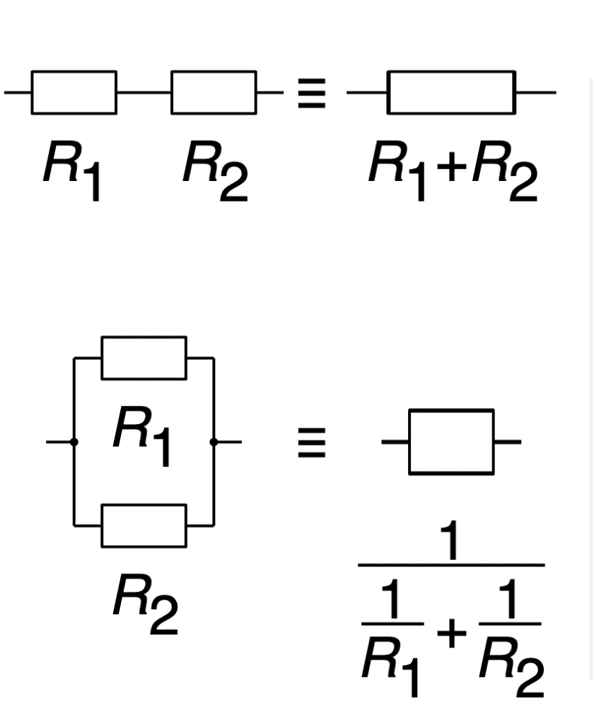
This image from wikipedia greatly sums up the characteristics of resistance in a series vs parallel:
Summary Before Project
What’s fascinating about this, is you can actually create different resistance values even if you may not have a specific resistor laying around. For example, if you wanted/needed a resistance of 400Ω, you can put 2 200Ω resistors in series, or 2 800Ω resistors in parallel. You can also reduce a more complicated circuit into a simpler one by reducing series/parallel resistors into a total resistor. For practice, I recommend working through some examples on https://www.electronics-tutorials.ws/resistor/res_5.html where there is a step by step breakdown of combination circuits (you should also check out the other tutorials on Series and Parallel circuits if the topic is still a little bit hazy). You will encounter resistors in series and or parallel many times over the crash course and if you continue on in the hobby electronics because there are so many basic circuit building blocks that leverage these basic concepts to achieve a goal.
Phew, Now Really onto the Project
In this project, use a 7-segment display to represent the current state the system is in (you can use numbers like was done in lesson 2 of this crash course, or anything you wish, goal is learning here so be creative). When a button is pushed, it changes the state you are in. Each state is represented by 8 LEDs. It’s up to you how you decide what each state means with regards to the LED lit up or not.
Again this project is for learning, and I am leaving the project description vague as possible. But to help spur some thinking, say I want to program a very simple (and boring) system, where I have 8 total states. The following state chart represents my very boring and simple example:

In this boring implementation of this, we simply go in a circular loop of 0-8, lighting a single LED as we go. But please be more creative with your project. Maybe have a wave like state, continously light up LEDs 1-8 until all were lit and then start shutting them down one by one in a LIFO (last in first out order). Or a FIFO order. Or each state can even be animations in and of itself, where initial state just lights up LEDs one at a time with a second in between, state 1 may be a chasing animation where you light up 1 “running away” from another LED with each passing second.
The possibilities are really endless here, so just start tinkering!
If you ever feel stuck with how the wiring should go, going back to either Lesson 1 or Lesson 2 of the crash course should help.
Feel free to share your designs and videos (and code if you wish) on the circuit fanatic Facebook page (https://www.facebook.com/Circuit-Fanatic-103372208107053). Like the page and follow if you haven’t already if you wish to have some more community as you work through this Arduino crash course.