Arduino Crash Course
Welcome to Lesson 4. We are moving along. Please leave any comments if you have any questions (or you can fill out the contact form if you prefer to contact me directly.
In lesson 3 of the crash course, we utilized Serial communication for the first time to output the distance between an object and our sensor. In this lesson, we will use a 16×2 LCD screen to provide output. Where will we get what to display? The Serial connection, but instead of this time, we will actually be reversing the direction where we type something into the Serial monitor -> data is pushed to USB connection -> into the RX pin on the Atmega -> processed by microcontroller (thanks to the code we will write) -> pushed to the LCD. This lesson will also be the first time we leverage the use of a pre-built library that we will need to import into our code.
01
Parts Needed
- Arduino Uno
- Potentiometer
- LCD Display (compatible with the Hitachi HD44780 driver)
If you purchased the starter kit from Lesson 1 or the Crash Course home page, the LCD display should be included.
02
What is This LCD Display
This LCD Display is a Character LCD Display. What does that mean? Well there are individual spots dedicated to different characters to display text. How does this differentiate between a graphical display (such as your monitor or TV)? Well it’s simple, a graphical LCD has all the pixels connected together so you can color any pixel to make more complex characters and/or graphics. Each character box consists of 40 pixels (5 pixels wide, 8 pixels long)
Benefits of Character LCD Display vs. Graphical LCD
Simplicity! This may sound counter intuitive to what we are trying to learn, but there are many projects where we don’t need (or even want) the ability to draw and manage an entire pixel space (even with the help of libraries). In this tutorial, we will be using a 16×2 or simply a 16 columns by 2 rows of characters (max 32 characters at a time). Need more characters to display, you can get another common Character Display LCD of 20 (columns) x 4 (rows) for 80 max characters displayed at a time. Also, with the library we are going to use, it allows us to scroll left (or right) so we can technically have an unlimited number of characters (just 32 characters will displayed at one time).
I want to take the time here to discuss how complex the operation we are doing here that is completely abstracted away for us by the LiquidCrysal library we will use. I highly recommend you looking at the documentation of this library. And if you are truly brave (or want to learn how it’s doing this magic), look at the source code itself (https://github.com/arduino-libraries/LiquidCrystal/tree/master/src). Don’t worry if you don’t understand how the code is working completely at first glance, but the best way to learn new things is seeing how it’s done “under the hood”, especially in a library that is well documented and widely used.
03
Watts That?
Before we get into further discussion of how to connect the LCD and what each pin means, let’s take a break and go over a common way to measure energy (or power). Watts is a very easy calculation once you know the voltage and the current of a circuit:
Watts = V * I
So what’s the big idea? Why calculate Watts? Well, the biggest reason to calculate watts is because it normalizes the energy usage into one characteristic. For example, say we had a 110v (normal AC in US) with a 20 milliamp load attached to it. This will be 2.2W (remember milliamps are .001 of an amp) of energy to run this load. Now say a load off of a 5v power supply is 200milliamps, the total wattage here is actually 1W of power. There is significantly more current (10x more current) flowing through 5V circuit, but the actual watts of power is more than half that of the load attached to the 110V. Without getting into too much detail here, but having lower amperage has some major benefits being the thickness (or gauge measured in AWG) of the wiring needed to safely carry that current. This is very common in solar arrays and battery pack building, the higher the voltage, the more watts it can produce with lower amperage (hence lower wire gauges) than similar wattage systems at lower voltages.
In this Arduino Crash Course, we won’t go into building or controlling heavy loads, so dupont wires (typically 22AWG) is more than enough to safely connect all parts. But it is crucial to understand the whole picture, especially since chances are you will be interested in the future to delve into LED strips (a 5M LED strip with 300 RGB LEDs on supplied with 12V can pull upwards of nearly 6amps of current – definitely can’t use 22AWG wires for that as that will be a significant fire risk).
04
Back To Character LCD Display
OK. After our detour of how to calculate watts, and it’s importance, time to get back onto the lesson of the Character LCD Display. You may be wondering why a potentiometer is listed as a necessary component for this lesson! Well if you look back to Lesson 1 of this Arduino Crash Course, you will know that a potentiometer is an adjustable resistor, so can you think of any reason why it will be included in a lesson about an LCD display? If you guess that it can control the contrast (how dark or light) the background of each character block is, then you are correct! Pat yourself on the back. Missing potentiometer is the most common issue I have seen people have when trying to utilize this display.
Now, you may be wondering, why doesn’t the LCD display have a known resistance needed to get the perfect contrast so you would only need to place a single resistor instead of needing a way to adjust the contrast. And that would be a great assumption to make, but each LCD display may be slightly different than others, so one resistor may work great for one, but not optimal for the next display. If you measured the resistance of the potentiometer with perfect contrast, and replaced it with a single resistor and use the same LCD display, then it will stay at the same contrast level (although you will lose the flexibility of being able to change the contrast in different light conditions and/or different set of eyes!).
OK. Let’s go through the pins:
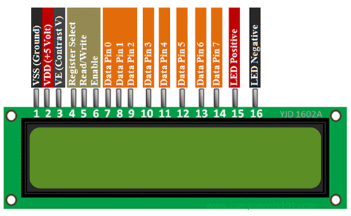
Starting Left to Right:
- VSS (Ground) – This is the ground terminal of LCD circuit
- VDD (+5V) – This is the supply pin for the LCD. As it states, we need to supply 5V to it
- VE – Contrast – Remember the potentiometer, well this is the pin to control the contrast
- Register Select – We will go into more details of what Registers are and how microcontrollers (and other more complex ICs) store basic data. For this lesson, just view it as a way to select which segment of the display we want to “write to” (this is abstracted away in the LiquidCrystal library). This will change between command and data registers within the LCD display.
- Read/Write – this pin is to tell the LCD display whether or not you are writing or reading from the register selected. Since we will be only writing to this display, we will just connect this to ground (0V is Write, 5V is Read)
- Enable – This pin will fluctuate (thanks to the LiquidCrystal display) to ack data transmissions were successful
- DataPins [0-7] – These are all the data pins that are being sent (since we are writing) from Arduino to the LCD display microcontroller. We will only use this LCD display in 4-bit mode, so we will only connect to 4 of the data pins (instead of all 8). Running it in 4-bit mode takes longer to transmit the data (still faster than the human eye) and also saves us from using 4 extra GPIO pins to control this display. Later on the Arduino Crash Course, we will go over a very common IC called SN74HC595, which is an 8 bit shift register which allows us to send out 8 bits using only 1 pin!
- LED Positive – Voltage in for the LED backlight (optional)
- LED Negative – Ground for the LED backlight (optional – although must be connected to ground if LED positive is connected).
OK, so now we know what each pin represents on the LCD display, try to think of how you will connect Arduino to this LCD display.
05
Let’s Build

Can you spot anything wrong with this wiring diagram? Hint: keep in mind the backlight is an LED! So we should place a resistor between either the 5v out of arduino to the LED Positive, or between the LED Negative and the ground.
Also, if we look at the diagram, you will notice we are using data pins 4-7 as our 4 bits (important to note this when we use the LiquidCrystal display in our code).
Take a few minutes and try to understand each component and why it’s connected the way it is. While doing that, try to think of how we are going to write code (leveraging the LiquidCrystal library) before just jumping to the code. Start by listing out the GPIO pins like we have done in previous lessons of this Arduino Crash Course.
06
Great! All Wired Up! Let’s Code!
Let’s go through the GPIO pins we are using on the Arduino and note where it’s connected:
- Pin 12 – To Register Select
- Pin 11 – To Enable
- Pin 5 – To Data4
- Pin 4 – To Data5
- Pin 3- To Data6
- Pin 2 – To Data7
If you notice here, we didn’t actually specify which pin is INPUT vs OUTPUT. Why? Well the LiquidCrystal display actually takes care of all of that for us, but we are only writing to the display, so all these GPIO pins will be output to the LCD display (with the exception of the enable – which the LCD display will make HIGH when it ack’s data transfer).
For the code, since we are using only 4 bit mode, we will use the following constructor (source https://www.arduino.cc/en/Reference/LiquidCrystalConstructor):
LiquidCrystal(rs, enable, d4, d5, d6, d7)
Notice, that this LiquidCrystal library only allows the use of Data pins 4-7 if using in 4 bit mode. So if you wired your connection to use Data pins 0-3, you will need to rewire to connect to these 4 data pins.
Ok. Now let’s start with an include statement and the defines for our pins:
#include <LiquidCrystal.h>
#define RSPin 12
#define ENPin 11
#define D4 5
#define D5 4
#define D6 3
#define D7 2
The first line includes the LiquidCrystal library and allows our sketch to then utilize all the functionality of that library. The next lines are optional, but makes code much cleaner and easier to read.
Now that we have defined everything, let’s go ahead and initialize everything we need in the setup method:
LiquidCrystal lcd(RSPin, ENPin, D4, D5, D6, D7);
void setup() {
  lcd.begin(16,2);
  lcd.print("hello, world!");
}
As you can see we actually define the LiquidCrystal by calling the constructor outside of the setup method. Why? Because we want to use the same object instance inside the loop as well. As noted in the documentation of the LiquidCrystal display, it says we need to call begin before trying to write to the Display, and the begin function takes number of columns and number of rows the LCD display has (https://www.arduino.cc/en/Reference/LiquidCrystalBegin). Note, if we wanted to only write to the first line, we could’ve just said the display is only 1 row (or similarly if we wanted to only write to the first 8 columns, we could have called the begin method with just 8 columns).
But what are we missing in the Setup? Remember, we wanted to take input from Serial. So we also need to initialize the Serial interface. Look back on Lesson 3 of the Arduino Crash Course if you forgot how to initialize Serial (or better yet, go straight to the Arduino documentation).
Now that we have setup our LCD and initialized our Serial Communication, time for the loop function. In this function, we want to take whatever was inputted from the Serial communication (via the Serial Monitor) and display it on the LCD. How can we do this? Make it a point to always check the documentation. Serial documentation lists a bunch of different functions we can use, but the readString function looks most promising (https://www.arduino.cc/reference/en/language/functions/communication/serial/readstring/).
Let’s get writing!
void loop() {
  while(Serial.available()) {
    String in = Serial.readString();
    Serial.println(in);
    lcd.display(in);
  }
}
That seems easy enough right? But what is this doing. We are checking if Serial is available (this is necessary, before we call the readString function). Once we get the input string, we then echo it back through the same Serial Communication (we receive it via the RX pin, and we send it back out via the TX pin). We then display it on the LCD.
There are several key things that are actually wrong with this code that I want you to work through. To help, I will point out 2 big issues:
- readString() times out (default is 1 second, but that can be changed using setTimeout function). The code needs to handle the case if it times out, such as printing an error message or just simply keeps the previous message on the screen until new input is received. Another different way of handling this is to consistently feed whatever is fed into Serial one character (or 1 byte really) using the Serial.read function and pass that directly to the LCD display. If taking this approach, you should have a serial command that clears the LCD display (or a button that clears the display).
- readString does not cut the number of characters at all. So if we have more than 32 characters, we either will have a chopped view of the first 32 characters, or we can leverage the scrollDisplayLeft() or scrollDisplayRight() of the LiquidCrystal library
I will leave it up to you to finish the code to fix these 2 major issues yourself. As stated before in this Arduino Crash Course, this is not made to simply provide you with solutions, but to provide you with explanations and resources to solve problems on your own.
07
What’s Next
Great! You were able to solve the 2 issues with the code in the previous section. How can you expand on this lesson while leveraging other lessons of this Arduino Crash Course?
- Connect a button to the Arduino where the button will control whether or not to clear the LCD display (some code changes will need to be done, but you should have these tools under your belt from previous lessons in the crash course to be able to do this).
- Connect a rocker switch to the LED backlight. This shouldn’t require any code as it will just be a circuit addition.
- Set up a Serial communication commands that will clear the screen and/or flip the LED backlight on/off. This will require rewiring the LED backlight to a GPIO pin and setting it as HIGH or LOW depending on if it is off or not. For example, setup the characters “ZZZCLEAR” as a clear command and “ZZZTOGGLE” as the LED toggle command. The commands themselves can be anything. You can even put the display as a command i.e. “DISPLAY=This is text to display.”, but this will obviously make your most common use case more complicated.
I hope you enjoyed this lesson and the excitement is continuously growing as you work through this Arduino Crash Course. See you next time!