Lesson 2 – I want to Rock(er)!
Lesson Overview
Another lesson, more LEDs to control (everyone loves LEDs). In this lesson we are going to go over rocker switches, a photocell resistor, and get into a common component containing a system of LEDs known as a 7-segment display. This lesson won’t go into the same level of detail as the previous lesson (as it is assumed you have a solid understanding of what was done in Lesson 1 of the Crash Course, so go back to it if you want to see an explanation if you don’t understand some concepts here).
In this lesson, we will control an LED via a rocker switch, control the brightness of an LED with a photocell, and produce a simple counter using the 7-segment display that will consistently loop through 0-9 with a push of a button.
Parts Needed
If you purchased a kit like mentioned in the first lesson of the crash course, you should have the components already needed for this project as well.
- Arduino Uno
- 2 220-ohm resistors
- 1 SPST button (Single Pole, Single Throw)
- 1 Photocell
- 1 Rocker Switch
- 2 LEDs (any color will be fine, but don’t use an RGB LED)
- 1 7-Segment Display (common cathode)
- Wires (dupont connectors wires are most commonly used)
- Bread Board – optional but extremely helpful for all prototyping
Parts Explained
Photocell – This tiny component is such a cool little component. The photocell will basically change it’s resistance based on the amount of light present. In complete darkness, the resistance is the highest, while as more light is present, the resistance from the photocell drops. In a way, that makes this component similar to the potentiometer discussed in first lesson of the crash course in the way that it is a component that provides a variable resistance to the rest of your circuit.
Rocker Switch – The rocker switch is well known because many housing light switches have rocker switches. A rocker switch is basically a component that is either on (allowing electricity to flow by connecting the pins) or off (electricity does not flow to the attached circuit). This should sound familiar as well if you read Lesson 1 of the Crash Course. A button is basically the same underlying as a rocker switch. Think if you taped a button down as the “on” state, and then removed the tape as the “off” state.
7-Segment Display – Whoa! That’s a lot of pins to connect to! Don’t be too overwhelmed with the number of pins for this device. Why? Well, because each pin can be viewed as power source to an LED (yes that’s right) within the 7-segment display. A common-cathode just means that all the LEDs internally share the same cathode (negative). Look at the diagram below showing each LED as well as the connection pin (for most common) displays out there:
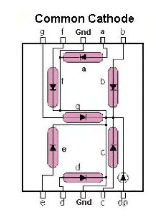
Here we can see each pin and which LED it represents, which we will need to know when we connect this to Arduino and how to properly light up a segment we want to light up.
Note: Even though this is commonly called a 7-segment display, there is a decimal point, so there is in essence 8 LEDs to control.
Let’s Build
Before you immediately jump into the provided wiring diagram, try thinking through it yourself on how you should connect the pieces. Go ahead and connect it that way. If you truly want to learn, you got to do it yourself. I purposefully left a wrong diagram in first lesson of the crash course to try to make this point, but don’t just blindly plug in any solution you see (well, if you do, you simply won’t ever learn what you are truly doing). If you just want to see results and not learn, then really what’s the point!
Without further adieu:
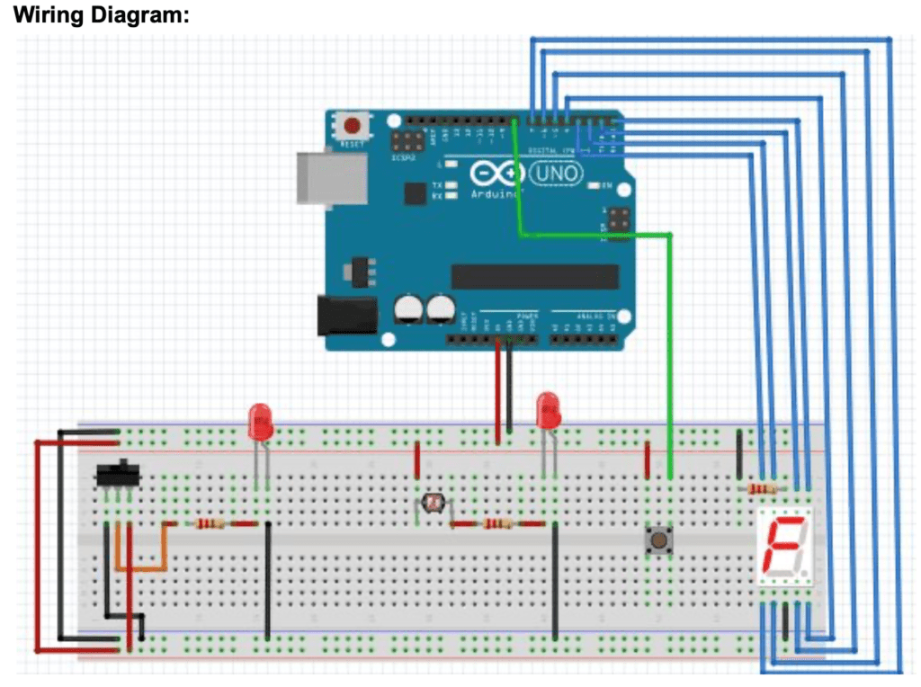
Does it come close to how you connected it? If you didn’t get the exact IO pins I used to connect to the Arduino, than that is fine (remember the actual IO pin we use only matters in the code). And once again, we see a major issue with this diagram. Can you spot it? If you took the first lesson of this crash course, it should be rather apparent. The LEDs are both improperly connected. Always remember the longer leg of the LED is the anode, and should be connected to the positive side, and the shorter leg should be connected to the ground. Always double check your connections for all polarized components!
Walkthrough
First we will start with the button. In the first lesson of the crash course, we did not need to connect the button to a GPIO pin, but now we are using it as an input, so we need to include it. But similar to first post, the wiring diagram is not using the diagonal pin. This lesson of the crash course we will go over what is considered a pull-down resistor. Look at how to properly set up the button here with a pull down resistor (taken from https://www.arduino.cc/en/tutorial/button):
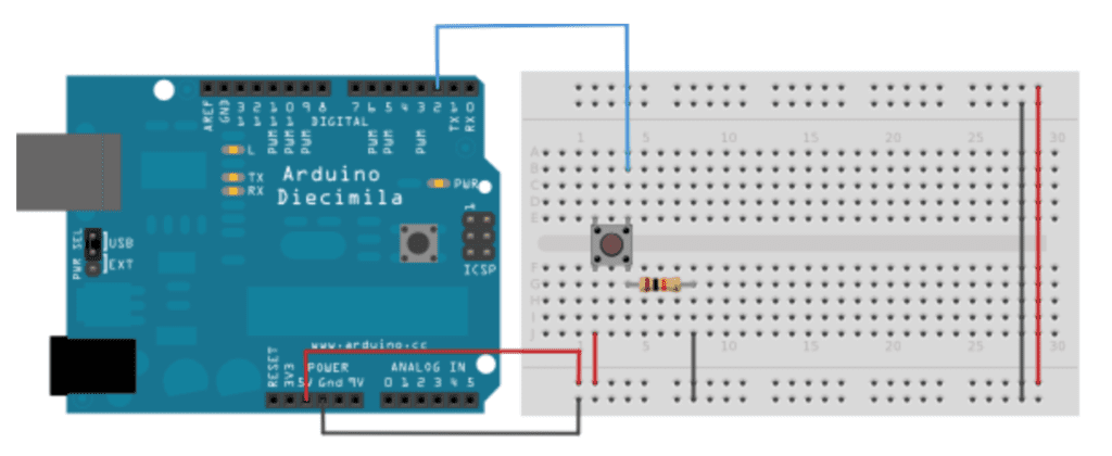
Here we see the button is connected to 5V and Ground (via a resistor) on the same side of the button. This resistor (10k Ohm is used in picture) is pulling the unpressed button value to Ground. But when the button is pushed, the contact inside will provide 5V to the GPIO pin
I recommend checking out that link as pull-up resistors are discussed as well and there is sample code in there on how to read the value of the button.
The rocker switch connection really depends on what type of rocker switch you have. Remember SPST button description in lesson 1 of the crash course? Well if you have a 2 pin Rocker switch, this is very similar where the 2 pins are connected in the “on” state. If you have a 3 pin Rocker switch, than chances are you have a SPDT (single pole double throw) switch. This means you can actually connect 2 different circuits for both states “on” and “off”. In the diagram we have a 3 pin, but we connect the “off” flow back to ground. NOTE: we should really have a resistor to ground and not connect directly to ground. Similar to the pull-down resistor you saw with the button above.
In the “on” phase, we connect the 5V from the rocker switch -> 220ohm resistor -> anode of LED. This should appear similar to what we did in Lesson 1 of the crash course with the button connection.
Moving onto the photocell. One leg is connected to the 5V source, the other leg is connected to 220ohm resistor->anode of LED.
Finally we get to the elephant in the room. The 7-segment display. It’s not nearly as bad as it looks. If you look back to the diagram of the 7-segment display up, you will see the pins representing a segment on the 2 outermost pins on each side and the ground pins are the middle pin on both the top and bottom of the display. One thing to notice here is that the resistor is actually connected to the ground pin instead of into the anodes of the LEDs. This is important to note that the resistor (generally) does not matter where in the circuit it is placed, as long as it’s present within the circuit. We could put 8 individual 220ohm resistors into each anode of each segment and it would be identical, but since we know that all LEDs in the display have a common cathode, we can simply place 1 in the cathode. Note: This will also work if you reversed the resistor on the other LEDs in the diagram and had the resistor connecting the cathode to the ground.
Great! All Wired up, Let’s Code!
So in the first lesson of the crash course, I just posted the whole code base. Each lesson going forward, it’s best to try to write the code yourself first and to try and keep from just blind copying and pasting, I will break down all code future lessons of this crash course into sections with a description of what is happening.
Before we get started, let’s just start with an inventory of the IO we have in place for this lesson:
- Pin 8 – INPUT (button)
- Pin 7 – OUTPUT (Segment ‘e’ in Display)
- Pin 6 – OUTPUT (‘d’)
- Pin 5 – OUTPUT (‘c’)
- Pin 4 – OUTPUT (‘dp’)
- Pin 3 – OUTPUT (‘g’)
- Pin 2 – OUTPUT (‘f’)
- Pin 1 – OUTPUT (‘a’)
- Pin 0 – OUTPUT (‘b’)
This is always a good practice to just jot down your wiring so you not only know whether each pin is Output or Input, but also know what it is connected to. So knowing this, try to write the setup method of your Arduino sketch.
void setup() {
  pinMode(8, INPUT); // initializes digital pin 8 as an input
  pinMode(7, OUTPUT); // initializes digital pin 7 as an output
  pinMode(6, OUTPUT); // initializes digital pin 6 as an output
  pinMode(5, OUTPUT); // initializes digital pin 5 as an output
  pinMode(4, OUTPUT); // initializes digital pin 4 as an output
  pinMode(3, OUTPUT); // initializes digital pin 3 as an output
  pinMode(2, OUTPUT); // initializes digital pin 2 as an output
  pinMode(1, OUTPUT); // initializes digital pin 1 as an output
  pinMode(0, OUTPUT); // initializes digital pin 0 as an output
}
Now before we get any further, remember what we are trying to do here with regards to the 7-segment display (keep a count of how many times the button has been pushed). For this, we will need a variable to keep the state of how many times a button has been pushed. So outside of the setup method, let’s declare and initialize an integer like so:
int count = 0;So why outside of the setup method? Well we have to worry about scope of the variable. This is a global variable that needs to be read with each iteration of the loop method where we will use this variable. So why not declare and initialize in the loop method? Well if we did that, the variable will be redeclared and reinitialized to 0 every time the loop function is called (basically making it always 0). We can however just simply declare the variable outside of the setup method, and then initialize it within the setup method such as this:
int count;

void setup() {
  count = 0;
  ...
}
Now let’s work on the loop method.
void loop() {
  int val = digitalRead(8);
  if (val == HIGH){
    count++;
    count = count % 10;
  }
  if (count == 0) {
    drawZero();
  } else if (count == 1) {
    drawOne();
  }
  ...
  ...
  } else if (count == 9) {
    drawNine();
  }
}
First we read the value of the button (pin 8). If it is HIGH, we increment the number of times it’s been pushed. The next line uses the modulus operator, which simply a fancy word for the remainder. So if we take the count and divide by 10, the remainder should always be between 0 and 9. Perfect!
Then we should have a bunch of if / else if blocks to draw the numbers based on the count. I will help with the writing of the draw zero, but will leave the rest to you to write and work around with.
So, we want to draw a 0 on the 7-segment display? If we scroll back to the diagram of the 7-segment display, we see that we need to light up (write HIGH) on segments ‘a’, ‘b’, ‘c’, ‘d’, ‘e’, ‘f’. If we look back on our wiring, we will see in order to do this, we need HIGH on pins 1, 0, 5, 6, 7, and 2 and LOW for the other pins (3 and 4).
void drawZero() {
  digitalWrite(3, LOW);
  digitalWrite(4, LOW);
  digitalWrite(1, HIGH);
  digitalWrite(0, HIGH);
  digitalWrite(5, HIGH);
  digitalWrite(6, HIGH);
  digitalWrite(7, HIGH);
  digitalWrite(2, HIGH);
}
Repeat the same process for drawOne() – drawNine().
Why Am I Getting an Error When Uploading?
Chances are you are getting an error uploading the sketch to the Arduino (especially if you have wired the circuit first before uploading the sketch). This is because pins 0 and 1 on the Arduino are actually used by the Rx (receive) and the Tx (transmit) pins for the serial communication between the Arduino and the USB connection. Therefore, if have these pins in any other state other than floating (i.e. not connected), and you try to upload your sketch via a USB connection, you will always have an upload error. How to fix this? Well, it is actually common practice to not leverage pins 0 and 1 on the Arduino if you can avoid it (there are so many more GPIO pins to use). So for this lesson, simply just choose 2 other pins (and make sure you update the code accordingly!). If you really wanted to use pins 0 and/or 1 in your sketch as a generic GPIO pin and you want to upload sketch via USB, simply disconnect the pins 0 and 1 while it is uploading! Once uploaded, you can place the pins back. How does this work, well the USB is no longer communicating to the Arduino after it has finished uploading the program (unless you are using some sort of Serial communication to be discussed in future lesson to help with debugging). The USB is simply providing the 5v power the microcontroller needs. And since the program has been “burned” into the microcontroller flash, you can unplug the USB wire, plug back in the pins, and then reconnect the USB cable and the program that was previously uploaded will run.
As you will see in this course, I am making you fall for these traps on purpose. Not to be mean, but to be teaching moments. You learn more by failing and understanding than you do by succeeding (especially if you are “succeeding” just because you are copying and pasting someone else’s work).
What’s Next
Congratulations. You got through the second lesson of the crash course and you are started to be a master of LEDs! I hope your mind is racing with all the cool things you can do with just the knowledge you learned from these first 2 lessons!
Want some more things to trial out? Try to solve the drawing of the segments using an array solution (this solution will actually remove the need to have 10 separate functions for each digit). There is several ways of doing this, but I think the easiest is to represent the each digit with a single byte representation representing which segments should be on/off. For example, if we take the segments necessary to make a 0 (pin 0, 1, 2, 5, 6, 7 as HIGH), we can represent this in binary as 0b11100111 (0xE7 in HEX, or simply 231 in base 10 notation), therefore we can have an integer array with 10 elements (representing 0-9) where the first element is 231 (calculate the other elements yourself). This is definitely a good exercise if you have never converted between binary and decimal notation, but also learning bitwise operations will make your development easier (in the digital world, we are dealing with just a bunch of 0’s and 1’s after all).
Need something a little bit simpler, or want more? How about you change the 7-segment display to spell out your name one letter at a time? Or we can leverage the decimal point in these segments to actually count to 20 (0-19), by lighting up the decimal means we already looped 1x through the digits.
Finally, try working with a pull-up resistor. Choose one of the components (the button is probably the easiest as that’s the component we used to describe pull-down resistors), and connect the component to a pull-up resistor (i.e. HIGH for when it is unpressed, LOW for when it is pressed). If done properly, you should see the LED connected to the button is always on, until the button is pushed and the LED is then turned off. How is the wiring different? If you can start to see and think in terms of “default state” such as LOW or HIGH, it will go a long way when working with more complex components.
1 thought on “Arduino Crash Course – Lesson 2”