Arduino Crash Course
Decided to spice it up the design with this lesson, let me know if you like it more or want to go back. I am always looking to improve this Arduino Crash Course to make it fun.
Anyway, onto lesson 3 of this crash course. What if I told you this lesson you are going to be using over 40 electrical components in this lesson? Don’t worry, a lot of these components are actually found within the sensor we are going to be using: the HC-SR04 Module (more commonly known as the ultrasonic measurement). Now hooking up this module is fun, but we will dive into the schematic and circuitry that makes up this module instead of just plugging it into our Arduino and getting the distance between objects.
01
Parts Needed
Going forward in all future lessons of this crash course, I won’t list breadboard and wired, it’ll just be assumed we need them for all projects!
02
What is The HC-SR04
This nifty little sensor is simply ultrasonic distance sensor. It measures distances by the 2 knob-like components (one transmits, one receives). You can think of it as a speaker and a microphone combo, although the soundwave (40kHz or 40000 times per second!) it sends will not be audible by humans. So let’s look at the schematic of this sensor:
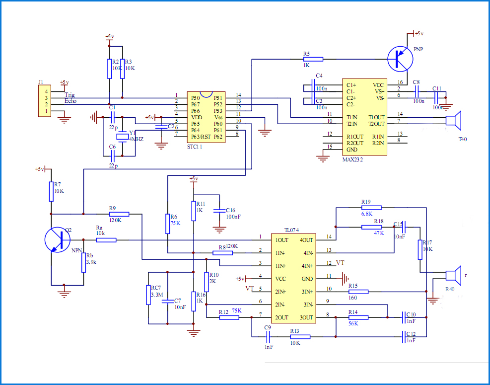
We won’t go into details of all the components in the schematic in this lesson fo the crash course, but will cover another major component present in almost all circuits, and that is the capacitors (shown in the schematic as 2 straight lines with a gap and labeled with a C_ where the underscore is a number of the capacitor). There is sometimes confusion on what a capacitor is for beginners, and most of the time I hear people saying that a capacitor holds current. This is not true, a capacitor simply is a storage of energy. In a way, a capacitor is like a rechargeable battery in the sense that you can charge it and discharge it. One use of capacitors that is common in almost all circuits is the idea of a bypass capacitor. Read any datasheet for any IC (integrated circuit), and chances are in the design recommendations, it will tell you to place a bypass capacitor as close to the power source input as possible. Why? Because a bypass capacitor is a quick and easy way to eliminate some noise on the DC signal in.
There are different kinds of capacitors out there, and there is a lot of already useful information on the web to continue your research of them, but this site sums it up perfectly: https://www.explainthatstuff.com/capacitors.html
Moving on from the schematic, you see 3 rather large boxes with several connections into them. These are the 3 major components that do all the calculations for you so the module can provide the answer the user would want to know, how far away is that object?
- STC11F – This is another microcontroller and is the brain of the module (similar to the Atmega328 is to the Arduino). It takes in a user input, and sends out very specific user output on the pins. If you are interested in learning about this microcontroller, the datasheet can be found here: http://www.stcmicro.com/datasheet/STC11F-10Fxx-en.pdf)
- MAX232 – This part is driving the transmitter of the ultrasonic wave. It is connected directly to the transmitter and it takes it’s instruction from the STC11F
- TL074 – This is an operational amplifier IC (op-amp for short). This takes in the input from the ultrasonic receiver, and as the name suggests, takes a very low amp (current) input signal, and outputs a larger amp output (current) signal. Op-amps are very common in things like speakers.
There are also a ton of resistors on the board, and 2 other components known as transistors which we will cover in another lesson of this Arduino Crash Course.
Now that we seen the schematic, take a look of the actual module you have. Look at all the components on the circuit board. Can you see how the schematic closely resembles the parts on the circuit board?
03
How Do I Trigger and Get Data from HC-SR04
The interface of the HC-SR04 consists of 4 pins: VCC, Trigger, Echo, and Ground. We should already know how to hook up the VCC and the ground (keep in mind, that this module has it’s own microcontroller, so we actually need to power it up as well, which is the reasoning behind the VCC and Ground). The trigger pin is an input to the module (therefore an output pin from the Arduino) which basically tells the module to send a wave out. To trigger it, you must set the Trigger pin HIGH for at least 10µ. The microcontroller will then tell the driver in the module to send out a pulse (it actually sends out 8 pulses out at 40kHz). The echo pin is output of the module (therefore your input), which will raise the line HIGH based on the formula of 58µS (.000058 seconds) per cm. This chart sums the full lifecycle of a request (this type of chart is usually called a timing chart, and we will get very familiar with them in future lessons of this crash course):
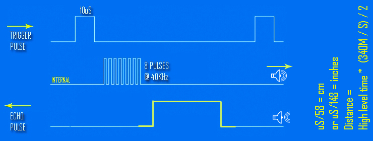
Now you may be wondering why 58µ per cm. Well this is tied to the speed of sound. When the transmitter sends these pulses out, the receiver will only pick up on them if those pulses bounce off what’s in front of it, and make it’s way back to the receiver (and then through the op-amp, to the microcontroller, which then calculates the distance and sets the echo pulse out via the echo pin).
There are limitations to this module. The transmitter can really only send pulses roughly 800cm and since in order for the ultrasound receiver to pickup the pulses it needs to bounce off of something, that means it can only measure roughly 400cm ahead of it. It also only has a measuring angle of 15º, so the object will need to be almost directly in front of the sensor, and the sensor works best if it’s on a flat surface.
04
Using Serial Communication
Remember in lesson 2 of this crash course, where we used pins 0 and 1 to connect the 7-segment display and it caused issues because those pins are also used as serial communication to upload the sketch onto the Arduino. Well, if you keep pins 0 and 1 free from GPIO, you can also leverage them to get data back off the microcontroller and into a serial monitor (a nice serial monitor is included in the Arduino IDE). What this means is we can leverage the Serial pins to write messages back to our computer that will be displayed on the Serial Monitor. https://www.arduino.cc/reference/en/language/functions/communication/serial/
This makes debugging a little bit easier as we can send over statements of what the microcontroller is doing in human readable format so we can know exactly what state the Arduino is in.
We will leverage the Serial interface in this lesson to write the distance an object is from the HC-SR04 sensor.
05
Let’s Build
Hopefully as you were going through this lesson, you were thinking about how to wire this module up to your Arduino. This wiring is much simpler than earlier lessons in this crash course, as you only need 4 wires (remember are leveraging the Serial interface to display the output):

06
Great! All Wired Up! Let’s Code!
Let’s go through what we need for this:
- Pin 12 – Echo – INPUT into Arduino (OUTPUT from Module)
- Pin 13 – Trigger – OUTPUT from Arduino (INPUT into Module)
So we should be comfortable with the setup method now, but I am going to show you another way that is very common when working with developing for microcontrollers (or in C or C++ in general) and that is to used define statements:
#define trigPin 13
#define echoPin 12
void setup() {
  Serial.begin (9600);
  pinMode(trigPin, OUTPUT);
  pinMode(echoPin, INPUT);
}
First off, to simply connect to the Serial communication, we just call Serial.begin() function which takes the baud rate. For arduino, you almost always want this to be 9600, because it can’t handle much faster communication speeds than that.
As you can see, we define trigPin to be 13 and echoPin to be 12. We can now reference them in our code as such. This makes code readability much better, especially when you get into larger and larger sketches for bigger projects.
Now let’s think about the loop. We need to trigger the module by sending out at least a 10µ HIGH on the trigger pin. After it’s triggered, we then need to read how long the echo pin is high for. There is a function called pulseIn (https://www.arduino.cc/reference/en/language/functions/advanced-io/pulsein/) that will give us the number of microseconds that the pin was in the HIGH state for.
Finally, we need to take that value of microseconds, divide it by 2 (since it is round trip time from transmitter -> bounce off object -> receiver) and then divide that by 74.1, to get the approximate number of inches. If we wanted to calculate in cm, we would just need to divide by roughly 29.
Finally we will write the distance in the Serial monitor:
vvoid loop() {
  delay(200);
  long duration, distance;
  digitalWrite(trigPin, LOW);
  delayMicroseconds(2);
  digitalWrite(trigPin, HIGH);
  delayMicroseconds(10);
  digitalWrite(trigPin, LOW);

  duration = pulseIn(echoPin, HIGH); distance = (duration/2) / 74.1;
  if (distance >= 200) {
    Serial.println("Out of range");
  }
  else {
    Serial.print(distance);
    Serial.println(" inches");
  }
}}
As we can see here, we actually just print out of range if the calculated distance is beyond 200 inches, but we may want to drop that to be roughly 150 inches, as we may get some false readings too far beyond 400cm (which is approximately 158 inches).
Also, you will see we simply call Serial.print if we want to send data through the Serial interface (println function simply adds a new line character as well).
07
What’s Next
You are becoming a master at this! To further explore what you can do, try using a 7-segment display as the out instead of Serial. You will have to get creative in how to display more than 1 digit, but that’s the fun part. Also, instead of just constantly be triggering the HC-SR04 module every 200 milliseconds in the loop (delay(200), how about connecting a button that triggers the module. You can configure this as an input into Arduino which then kicks off the process (sending a 10µ HIGH on the TRIGGER pin), or you can actually connect the button directly to the TRIGGER pin. What happens if you hold the button down too long? What happens if you quickly tap the button as fast as you can. 10µ is a very short period of time.
See you next time for the next lesson of the Arduino Crash Course
1 thought on “Arduino Crash Course – Lesson 3”