Arduino Crash Course

Welcome to Lesson 5 of the Crash Course. Please leave any comments or questions you have as comments directly on the post (or you can fill out the contact form if you prefer to contact me directly).  

If you are enjoying the crash course so far, please share with your like-minded friends and follow us on Facebook.

Let’s get onto the lesson.  In this lesson of the Arduino Crash Course, we will learn about motors, and control one type of motor known as the servo motor.  Future lessons, we will also control DC and stepper motors.  If you bought this kit from Elegoo which I recommended on the main Arduino Crash Course page, all the parts needed for these lessons will be included in the kit.

01

Parts Needed


If you didn’t buy the kit from Elegoo (or some similar kit made for arduino), please ensure the Servo motor can run with 5V in and does not require more current than an Arduino Uno GPIO pin can supply (40mA per pin).

02

What Types of Motors Exist?

There are 3 major categories of motors that each have advantages and disadvantages of each.

Servo Motor

Let’s start with the motor we will be using in this lesson.  A servo motor is actually (usually) a combination of 4 components: a DC Motor, a gearing set, a control circuit, and a potentiometer (or some other position form of a position-sensor such as a rotary encoder).  In other words, a servo motor is actually a DC motor that is self-contained, thus making it easier (usually) to use.  Servo motors typically have 3 wires: power, ground, and control.

Servo Motors unfortunately only rotate 180º (some rotate slightly more, but none will have rotate freely like the other motors).  Power to servo motors is continually applied, and because of this, servo motors will hold the position (holding torque), and the control circuit will control the current to the motor based on the data coming in through the control pin (more on this later).

Good examples of when to use a servo motor is for turning wheel axis for an RC car (since it only needs limited range and usually you won’t be turning a wheel beyond 90º in each direction to make a turn), or a rudder for a boat (similar reasoning).

DC Motor

A DC motor is simply a Direct Current motor (so theoretically, all other motors that run on direct current is a subset of DC motors).  DC motors have 2 wires, power and ground.  Because it doesn’t have a built in circuit control and a built-in position sensor, that needs to be taken into account if you need specific control of how far to turn a motor.  DC motors come in a variety of “flavors” based on how they are constructed.  We won’t go into too much detail on the different types of DC Motors, but if you are interested, https://www.quantumdev.com/brushless-motors-vs-brush-motors-whats-the-difference/.  

DC motors usually run at a much higher RPM (rotations per minute) than the other types of motors discussed here.  DC motors are controlled using PWM (more on this later), but instead of controlling the direction like a Servo Motor, PWM is used to control the speed of the motor.

A good example for a proper use of a DC motor is the propulsion motor to drive an RC car.

Stepper Motor

Stepper motors are, as the name suggests, are motors that move in steps.  The main characteristic (other than holding torque) is the granularity of the step (in either degrees, or number of steps in a full 360º rotation).  A stepper motor uses electromagnets arranged evenly around a central gear to define the position it is in.  

Stepper motors are typically slower motors, but are much more precise, due to the electromagnetic steps.  In a 200 steps/revolution stepper motor, it will always rotate exactly 1.8º each step it takes. 

Stepper motors are commonly found in CNC machines and/or 3D printing machines for controlling each axis. 

03

PWM – Pulse Width Modulation

Pulse Width Modulation (will be referred to as PWM from here on in this Arduino Crash Course) is just a fancy word that represents turning on/off a digital signal usually at a high rate.  PWM is used in many different ways, such as controlling motors, reducing energy waste when converting power, to controlling ICs or even LEDs. 

Before we go further, we must understand some terms.  A period is the amount of time in one cycle and is measured in Hz (Hertz).  So if you have a 100KHz frequency PWM at 50% duty cycle, that means that each period is 10µs consisting of 5µs of digital on (HIGH) and 5µs digital off (LOW).

We can see other examples in the following picture (from wikipedia):

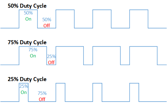
By looking at this, you may be visualizing how it can be used in a way to be more efficient in power conversions.  Hopefully you can also visualize how you can use PWM as a way to communicate.  If you have ever seen what have been called NeoPixel LED strips, the WS2812B IC connected to each LED uses a similar communication protocol to control the Red/Green/Blue of each LED.  We may get to controlling these in a future lesson in this Arduino Crash Course (or part of a more advanced post), but if you are interested the strip looks like this (I have this exact set and works great):


NOTE: You cannot power these (or most LED strips) with Arduino’s directly, but you can control them.  There are plenty of resources online if you want to try to build something with them.

PWM can also be used to simulate Analog, in essence you can make a simplified DAC (digital to analog conversion).  But being that DAC ICs are relatively cheap, and much more accurate than an Arduino can be, building a DAC using PWM from Arduino should be done strictly as a learning exercise and not part of a final design solution.


04

Back To Servo Motors

As stated earlier in this lesson, a servo motor has 3 connection wires: a ground (usually brown or black), power (usually red), and a control/signal (usually orange). 

Luckily for us, there is a Servo library available to allow us to focus on what we want to do as opposed to bog down on controlling the servo via PWM: https://www.arduino.cc/en/reference/servo. But as should be expected if you have been following along with this Arduino crash course, we don’t simple but we want to learn.  So let’s delve into the library code to see exactly what it is doing (https://github.com/arduino-libraries/Servo).

Let’s start with the Servo.cpp write function:

void Servo::write(int value)
{
  if(value < MIN_PULSE_WIDTH)
  {  // treat values less than 544 as angles in degrees (valid values in microseconds are handled as microseconds)
    if(value < 0) value = 0;
    if(value > 180) value = 180;
    value = map(value, 0, 180, SERVO_MIN(),  SERVO_MAX());
  }
  this->writeMicroseconds(value);
}

In this function, we see that we are resetting any value < 0 to 0 and > 180 to 180.  Then we see the map function which converts the degrees value (from 0º to 180º) to the servo min and max modulation (more details on this map function https://www.arduino.cc/reference/en/language/functions/math/map/).

If you peer into the writeMicroseconds function of the Servo class, you will notice a call of analogWrite().  analogWrite is the PWM magic (handled by Arduino library for you): https://www.arduino.cc/reference/en/language/functions/analog-io/analogwrite/.  

Please note, the Arduino Uno uses PWM on pins 3, 5, 6, 9, 10, 11 with a frequency: 490 Hz (pins 5 and 6: 980 Hz).  Also, since Arduino is 8 bit, the range you can send via PWM is 0-255 (2^8 – 1).  

Side Note: You may notice as you are perusing the documentation that the analogRead takes values between 0 and 1023.  Why? Well because the Arduino has a 10bit ADC (analog-to-digital converter).

05

Let’s Build

The wiring is very simple.  So why did we choose pin 9?  Well we need to use a pin that has PWM (again, reference https://www.arduino.cc/reference/en/language/functions/analog-io/analogwrite/ to know what pins can send PWM).  

Like said earlier in this lesson, and hopefully as you perused through the Servo library, you have confirmed that the Servo motor’s position is controlled by the pulse width.  The smaller the pulse width, the more counter-clockwise the servo motor turns and vice versa. 

Now that we have wired up our servo motor, try to think of code that will make the motor sweep from min to max to min and repeat.

06

Great! All Wired Up! Let’s Code!

Let’s go through the GPIO pins we are using on the Arduino and note where it’s connected:


  • Pin 9 – Output – Control of Servo (orange wire)

For the code, we look at the reference for Servo again and declare our Servo and a variable to hold the current position: 

https://www.arduino.cc/en/reference/servo

#define SERVOPIN 9

#include <Servo.h>

Servo theMotor;
int pos = 0;

Now our setup method is rather straightforward, we want to call the attach to our motor instance to the pin the motor is attached to.

void setup() {
  theMotor.attach(SERVOPIN)
}

Finally, we want to write our loop function.  Remember, servos can only go from 0º to roughly 180º.  So to go from min to max back to min, we just want to loop through each degree (we will increment/decrement by 5º at a time).

Let’s get writing!

void loop() {
  for (pos = 0; pos <= 180; pos += 5) { 
    theMotor.write(pos);              
    delay(30);                       
  }
  for (pos = 180; pos >= 0; pos -= 5) { 
    theMotor.write(pos);              
    delay(30);                       
  }
}

What’s with the delay?  Well, even though we set are commanding the motor to move 5º at a time, it takes time for the motor to physically move from where it was to where it needs to be.  One thing to take note of is the speed of the servo is the same no matter how many degrees it needs to rotate (try it out!).

07

What’s Next

Great! Another lesson down in the Arduino Crash Course.  We now know how to control servo motors! How can we expand this simple wiring to be more beneficial?


  • Connect 2 buttons to the arduino: a forward and reverse button, if the forward button is pushed, move the servo xº clockwise (increase the position) and if the reverse button is pushed, move the servo xº counter-clockwise.
  • Use the serial communication to print out the position (in degrees) that represents the state of the servo
  • If you are brave, try controlling the Servo using just the analogWrite function (i.e. don’t use the Servo library).

I hope you enjoyed this lesson and the excitement is continuously growing as you work through this Arduino Crash Course.  See you next time!  Again, if you are enjoying this Arduino Crash Course, please share with others and join us on Facebook.

Arduino Crash Course

Welcome to the 2nd Project of this Arduino Crash Course.  In this project you will leverage all the knowledge obtained through the first 4 lessons of this crash course to provide a solution without any wiring or code provided.  You can do it, I know you can!

Enjoying the Arduino Crash Course?  Follow us on Facebook and share with all your friends!

Before we jump into the project, I think now is a great time to talk about multimeters, and why everyone building electrical circuits needs one.

01

Multimeters – What Is That

A multimeter is a very important tool for every electronics hobbyist (in fact, every electronic hobbyist should have at least 2 of them – more on this later). 

If you don’t have a multimeter yet, I recommend purchasing this one by Klein Tools MM700.  If you want a cheaper multimeter at first, then I recommend the Klein Tools MM300: 


So why Klein Tools?  Klein Tools is a very reputable brand and these multimeters are well built and if taken proper care of will last forever!  I have had my fair share of cheap multimeters, and they don’t last long.  Trust me, get a Klein Tools, and you won’t have to worry about it breaking in the middle of a project (very frustrating!).

A multimeter is an all-in-one tool where you can measure voltage, amperage, resistance, and continuity testing (all of these explained below and how to do it with most common multimeters on the market).  

Before we get started, most multimeters have three inputs, but only two leads.  The middle input is usually the ground input, where you would want to plug in the black lead (NOTE: there is no physical difference in the leads that are colored Black and Red, it’s just common practice to use Black for Ground, and Red for Positive).  If you are measuring volts or small amounts of current usually less than 200mA (max is usually displayed on the unit itself, DO NOT EXCEED THE CURRENT LIMITS AS IT CAN BREAK THE MULTIMETER).  If you are ever measuring current, I would always recommend to connect it to the other input (usually 10A max).  Why?  Well because the left input with max Amps is usually fused, and the fuse may blow, but your multimeter itself will not be broken (would just need to replace the internal fuse).  With that said, I always like to put the leads back into the right side whenever I am storing my multimeter away.

02

MultiMeter – Measuring Voltages

One of the main functions of a multimeter is measure voltages (also known as a voltmeter).  It does this by placing the Positive lead (red) to the positive of what you are trying to measure, and the negative lead (black) to the negative.  Ensure that the ground (black) is connected to the middle input port on the multimeter, and the positive (red) lead is connected into right side (usually denoted by what it measures as well as a max Amperage it can measure).  

If you don’t have an auto-sensing multimeter, you will have a dial.  You will need to change the dial to that the expected measurement is below the value selected, but more than the next lowest available measurement.  For example, if you wanted to measure the voltage of a 9V battery, you will select 20V, because you are expecting around 9V, and 2V (the next lowest available option on most multimeters) would not be enough. 

If you are measuring and the multimeter is showing 0 (and you are sure the connection is proper), then you may have to change the dial to a higher (or sometimes lower) source.

You can measure whole circuits, or individual components for their voltage (note: ground doesn’t always mean 0V in this case, it’s just measuring the starting voltage and the ending voltage, and providing the differential as a measurement).  If you were to measure the voltage from the positive side of an LED, to and connect ground to the negative side of an LED, you will get the forward voltage of the LED.  Take the original voltage supply and subtract out the forward voltage, and you have the voltage dropout caused by the LED.  Go back to previous lessons in this Arduino Crash Course and measure it.  How close do your LED’s match the table provided in Lesson 1?

03

MultiMeter – Measuring Current

Like I said in the intro to this project, I always prefer to switch the red lead to the fused input whenever measuring current (even if I know the measured current will not even come close to the max I can measure on the right input). 

To measure current, your 2 leads are no longer positive and negative, but actually become a part of the circuit itself.  How this works is you break up the circuit you are working on, and connect the 2 leads to reform the “break” (in essence you are making the current flow into the multimeter).

I can’t stress this enough.  It is extremely important that you do not try to measure above the max rating given on the multimeter!  Even if you are on the fused input (who likes dissembling just to replace a fuse).  

To start measuring, disconnect all power and ensure that all capacitors in your circuit are completely discharged.  Once you are sure that the circuit is powered down, find a part of the circuit where you want to measure the current (I usually am testing the full circuit, so I will simply connect the red lead from the power source to the entry point of my circuit – or Arduino).  Granted, if you are using USB as the power source, this can get a little tricky unless, but you can measure the current from any of the pins or any other “sub-circuit”.  

You will need to adjust the dial, similar to how you adjusted it for voltages to ensure the multimeter knows the rough range of what it is measuring.


04

Multimeter – Measuring Resistance

Have a resistor where the bands are wiped off, or you can’t make out whether a color is brown or red or whatever?  Or simply you want to get the real value of the resistance with the tolerance already incorporated?

Multimeter can help.  First, switch back the red lead to the right input so we can measure Resistances.  Then on the dial find where the expected range is.  Then simply connect the leads together (much simpler if using alligator clips!).  That’s it.  The multimeter will calculate the resistance of the resistor for you.  

Now say you didn’t pay attention or you skipped Lesson 1 on Ohm’s Law, and you skipped the section on series or parallel resistance or simply too lazy to do the calculation.  Well you can use the multimeter.  Connect the leads of 2 or more resistors to each lead of the multimeter to get the parallel resistance value.  If you want to calculate the series resistance, well connect the multimeter to one leg of the resistor, the other leg will connect to the other resistor, and the last leg connect to the other lead.  Boom! Series resistance!

05

Multimeter – Continuity Testing

I honestly don’t think this is mentioned enough in the plethora of tutorials and how-to’s out there in the electronics hobbyist world.  This is by far my favorite feature of the multimeter and may be the one I use the most (make sure your multimeter you get has some sort of continuity testing on it). 

This is a very simple test where the multimeter will beep if the 2 ends are connected.  I use this all the time for all pins I solder to ensure that:

A.  There is a good connection from one end to the other

B.  There is no shorted pins (i.e. pin 1 is not touching anything else but pin 1).  

I am a creature of habit, but whenever I turn to continuity mode, I always test the multimeter is working by just touching the 2 leads together (this should always beep as the 2 leads are electrically connected).

Go back into other lessons in this Arduino Crash Course, and test some of the other components.  Buttons are always fun.  Remember when I said to always pick the pin diagonally from where you connected the first pin, well, you don’t have to if you know the other pin is not connected when the button is not pressed because there is no continuity.  Press the button down, and you should hear the beep as they are now connected.  Rocker switches, in the off state, no beep.  When flipped on, you should hear that beep because they are electronically connected.

06

multimeter – Summary

It’s almost impossible to get very far in this hobby without the use of a multimeter.  In fact, you will quickly notice the need for 2 multimeters (and sometime even 4 multimeters).  Perfect example of this is you want to measure the voltage and current of a circuit.  Well the multimeter can do one or the other at any given time, but have 2 connected at same time, and then you have the total Watts (review previous lesson of this Arduino crash course if you do not know what Watts are).

This all in one tool is the most important and valuable asset we have to analyze our circuits, so it is imperative to have one.

07

Project Description

OK.  It’s finally time to discuss the second project to be done in this Arduino Crash Course.  If you remember from Lesson 3 we learned about how to measure distance with the HC-SR04.  In lesson 4, we used a 16×2 LCD character display to show output.  

In this project, combine these 2 lessons to print out the distance an object is from the HC-SR04 and display the output on the LCD display.  

Once you have completed that, add a button to the schematic that toggles the distances between metric system (cm) to the imperial system (inches).  Add a rocker switch to the LED backlight.  

Finally, measure the current of the LCD display with the LED backlight on vs not on?  How much difference does the LED light make in terms of energy consumption.  Calculate the watts used in both scenarios.


Enjoy the Arduino Crash Course so far?  Join our facebook group https://www.facebook.com/Circuit-Fanatic-103372208107053/ and share this course to all your friends!


Arduino Crash Course

Welcome to Lesson 4.  We are moving along.  Please leave any comments if you have any questions (or you can fill out the contact form if you prefer to contact me directly.

In lesson 3 of the crash course, we utilized Serial communication for the first time to output the distance between an object and our sensor.  In this lesson, we will use a 16×2 LCD screen to provide output.  Where will we get what to display?  The Serial connection, but instead of this time, we will actually be reversing the direction where we type something into the Serial monitor -> data is pushed to USB connection -> into the RX pin on the Atmega -> processed by microcontroller (thanks to the code we will write) -> pushed to the LCD.  This lesson will also be the first time we leverage the use of a pre-built library that we will need to import into our code.

01

Parts Needed


If you purchased the starter kit from Lesson 1 or the Crash Course home page, the LCD display should be included.

02

What is This LCD Display

This LCD Display is a Character LCD Display.  What does that mean?  Well there are individual spots dedicated to different characters to display text.  How does this differentiate between a graphical display (such as your monitor or TV)?  Well it’s simple, a graphical LCD has all the pixels connected together so you can color any pixel to make more complex characters and/or graphics.  Each character box consists of 40 pixels (5 pixels wide, 8 pixels long)

Benefits of Character LCD Display vs. Graphical LCD

Simplicity! This may sound counter intuitive to what we are trying to learn, but there are many projects where we don’t need (or even want) the ability to draw and manage an entire pixel space (even with the help of libraries).  In this tutorial, we will be using a 16×2 or simply a 16 columns by 2 rows of characters (max 32 characters at a time).  Need more characters to display, you can get another common Character Display LCD of  20 (columns) x 4 (rows) for 80 max characters displayed at a time.  Also, with the library we are going to use, it allows us to scroll left (or right) so we can technically have an unlimited number of characters (just 32 characters will displayed at one time).  

I want to take the time here to discuss how complex the operation we are doing here that is completely abstracted away for us by the LiquidCrysal library we will use.  I highly recommend you looking at the documentation of this library.  And if you are truly brave (or want to learn how it’s doing this magic), look at the source code itself (https://github.com/arduino-libraries/LiquidCrystal/tree/master/src).  Don’t worry if you don’t understand how the code is working completely at first glance, but the best way to learn new things is seeing how it’s done “under the hood”, especially in a library that is well documented and widely used.  

03

Watts That?

Before we get into further discussion of how to connect the LCD and what each pin means, let’s take a break and go over a common way to measure energy (or power).  Watts is a very easy calculation once you know the voltage and the current of a circuit:


Watts = V * I

So what’s the big idea?  Why calculate Watts?  Well, the biggest reason to calculate watts is because it normalizes the energy usage into one characteristic.  For example, say we had a 110v (normal AC in US) with a 20 milliamp load attached to it.  This will be 2.2W (remember milliamps are .001 of an amp) of energy to run this load.  Now say a load off of a 5v power supply is 200milliamps, the total wattage here is actually 1W of power.  There is significantly more current (10x more current) flowing through 5V circuit, but the actual watts of power is more than half that of the load attached to the 110V.  Without getting into too much detail here, but having lower amperage has some major benefits being the thickness (or gauge measured in AWG) of the wiring needed to safely carry that current.  This is very common in solar arrays and battery pack building, the higher the voltage, the more watts it can produce with lower amperage (hence lower wire gauges) than similar wattage systems at lower voltages.  

In this Arduino Crash Course, we won’t go into building or controlling heavy loads, so dupont wires (typically 22AWG) is more than enough to safely connect all parts.  But it is crucial to understand the whole picture, especially since chances are you will be interested in the future to delve into LED strips (a 5M LED strip with 300 RGB LEDs on supplied with 12V can pull upwards of nearly 6amps of current – definitely can’t use 22AWG wires for that as that will be a significant fire risk).   


04

Back To Character LCD Display

OK.  After our detour of how to calculate watts, and it’s importance, time to get back onto the lesson of the Character LCD Display.  You may be wondering why a potentiometer is listed as a necessary component for this lesson!  Well if you look back to Lesson 1 of this Arduino Crash Course, you will know that a potentiometer is an adjustable resistor, so can you think of any reason why it will be included in a lesson about an LCD display? If you guess that it can control the contrast (how dark or light) the background of each character block is, then you are correct! Pat yourself on the back.  Missing potentiometer is the most common issue I have seen people have when trying to utilize this display.

Now, you may be wondering, why doesn’t the LCD display have a known resistance needed to get the perfect contrast so you would only need to place a single resistor instead of needing a way to adjust the contrast.  And that would be a great assumption to make, but each LCD display may be slightly different than others, so one resistor may work great for one, but not optimal for the next display.  If you measured the resistance of the potentiometer with perfect contrast, and replaced it with a single resistor and use the same LCD display, then it will stay at the same contrast level (although you will lose the flexibility of being able to change the contrast in different light conditions and/or different set of eyes!).

OK.  Let’s go through the pins:

Starting Left to Right:


  • VSS (Ground) – This is the ground terminal of LCD circuit
  • VDD (+5V) – This is the supply pin for the LCD.  As it states, we need to supply 5V to it
  • VE – Contrast – Remember the potentiometer, well this is the pin to control the contrast
  • Register Select – We will go into more details of what Registers are and how microcontrollers (and other more complex ICs) store basic data.  For this lesson, just view it as a way to select which segment of the display we want to “write to” (this is abstracted away in the LiquidCrystal library).  This will change between command and data registers within the LCD display.
  • Read/Write – this pin is to tell the LCD display whether or not you are writing or reading from the register selected.  Since we will be only writing to this display, we will just connect this to ground (0V is Write, 5V is Read)
  • Enable – This pin will fluctuate (thanks to the LiquidCrystal display) to ack data transmissions were successful
  • DataPins [0-7] – These are all the data pins that are being sent (since we are writing) from Arduino to the LCD display microcontroller.  We will only use this LCD display in 4-bit mode, so we will only connect to 4 of the data pins (instead of all 8).  Running it in 4-bit mode takes longer to transmit the data (still faster than the human eye) and also saves us from using 4 extra GPIO pins to control this display.  Later on the Arduino Crash Course, we will go over a very common IC called SN74HC595, which is an 8 bit shift register which allows us to send out 8 bits using only 1 pin!
  • LED Positive – Voltage in for the LED backlight (optional) 
  • LED Negative – Ground for the LED backlight (optional – although must be connected to ground if LED positive is connected).

OK, so now we know what each pin represents on the LCD display, try to think of how you will connect Arduino to this LCD display.

05

Let’s Build

Can you spot anything wrong with this wiring diagram?  Hint: keep in mind the backlight is an LED!  So we should place a resistor between either the 5v out of arduino to the LED Positive, or between the LED Negative and the ground.

Also, if we look at the diagram, you will notice we are using data pins 4-7 as our 4 bits (important to note this when we use the LiquidCrystal display in our code).

Take a few minutes and try to understand each component and why it’s connected the way it is.  While doing that, try to think of how we are going to write code (leveraging the LiquidCrystal library) before just jumping to the code.  Start by listing out the GPIO pins like we have done in previous lessons of this Arduino Crash Course.

06

Great! All Wired Up! Let’s Code!

Let’s go through the GPIO pins we are using on the Arduino and note where it’s connected:


  • Pin 12 – To Register Select
  • Pin 11 – To Enable
  • Pin 5 – To Data4 
  • Pin 4 – To Data5
  • Pin 3-  To Data6
  • Pin 2 – To Data7

If you notice here, we didn’t actually specify which pin is INPUT vs OUTPUT.  Why?  Well the LiquidCrystal display actually takes care of all of that for us, but we are only writing to the display, so all these GPIO pins will be output to the LCD display (with the exception of the enable – which the LCD display will make HIGH when it ack’s data transfer).

For the code, since we are using only 4 bit mode, we will use the following constructor (source https://www.arduino.cc/en/Reference/LiquidCrystalConstructor):

LiquidCrystal(rs, enable, d4, d5, d6, d7)

Notice, that this LiquidCrystal library only allows the use of Data pins 4-7 if using in 4 bit mode.  So if you wired your connection to use Data pins 0-3, you will need to rewire to connect to these 4 data pins.

Ok.  Now let’s start with an include statement and the defines for our pins:

#include <LiquidCrystal.h>
#define RSPin 12
#define ENPin 11
#define D4 5
#define D5 4
#define D6 3
#define D7 2

The first line includes the LiquidCrystal library and allows our sketch to then utilize all the functionality of that library.  The next lines are optional, but makes code much cleaner and easier to read.  

Now that we have defined everything, let’s go ahead and initialize everything we need in the setup method:

LiquidCrystal lcd(RSPin, ENPin, D4, D5, D6, D7);
void setup() {
  lcd.begin(16,2);
  lcd.print("hello, world!");
}

As you can see we actually define the LiquidCrystal by calling the constructor outside of the setup method.  Why?  Because we want to use the same object instance inside the loop as well.  As noted in the documentation of the LiquidCrystal display, it says we need to call begin before trying to write to the Display, and the begin function takes number of columns and number of rows the LCD display has (https://www.arduino.cc/en/Reference/LiquidCrystalBegin).  Note, if we wanted to only write to the first line, we could’ve just said the display is only 1 row (or similarly if we wanted to only write to the first 8 columns, we could have called the begin method with just 8 columns).

But what are we missing in the Setup?  Remember, we wanted to take input from Serial.  So we also need to initialize the Serial interface.  Look back on Lesson 3 of the Arduino Crash Course if you forgot how to initialize Serial (or better yet, go straight to the Arduino documentation).

Now that we have setup our LCD and initialized our Serial Communication, time for the loop function.  In this function, we want to take whatever was inputted from the Serial communication (via the Serial Monitor) and display it on the LCD.  How can we do this?  Make it a point to always check the documentation.  Serial documentation lists a bunch of different functions we can use, but the readString function looks most promising (https://www.arduino.cc/reference/en/language/functions/communication/serial/readstring/).

Let’s get writing!

void loop() {
  while(Serial.available()) {
    String in = Serial.readString();
    Serial.println(in);
    lcd.display(in);
  }
}

That seems easy enough right?  But what is this doing.  We are checking if Serial is available (this is necessary, before we call the readString function).  Once we get the input string, we then echo it back through the same Serial Communication (we receive it via the RX pin, and we send it back out via the TX pin). We then display it on the LCD. 

There are several key things that are actually wrong with this code that I want you to work through.  To help, I will point out 2 big issues:

  • readString() times out (default is 1 second, but that can be changed using setTimeout function).  The code needs to handle the case if it times out, such as printing an error message or just simply keeps the previous message on the screen until new input is received.  Another different way of handling this is to consistently feed whatever is fed into Serial one character (or 1 byte really) using the Serial.read function and pass that directly to the LCD display.  If taking this approach, you should have a serial command that clears the LCD display (or a button that clears the display).
  • readString does not cut the number of characters at all.  So if we have more than 32 characters, we either will have a chopped view of the first 32 characters, or we can leverage the scrollDisplayLeft() or scrollDisplayRight() of the LiquidCrystal library

I will leave it up to you to finish the code to fix these 2 major issues yourself.  As stated before in this Arduino Crash Course, this is not made to simply provide you with solutions, but to provide you with explanations and resources to solve problems on your own.  

07

What’s Next

Great! You were able to solve the 2 issues with the code in the previous section.  How can you expand on this lesson while leveraging other lessons of this Arduino Crash Course?  


  • Connect a button to the Arduino where the button will control whether or not to clear the LCD display (some code changes will need to be done, but you should have these tools under your belt from previous lessons in the crash course to be able to do this).
  • Connect a rocker switch to the LED backlight.  This shouldn’t require any code as it will just be a circuit addition.
  • Set up a Serial communication commands that will clear the screen and/or flip the LED backlight on/off.  This will require rewiring the LED backlight to a GPIO pin and setting it as HIGH or LOW depending on if it is off or not.  For example, setup the characters “ZZZCLEAR” as a clear command and “ZZZTOGGLE” as the LED toggle command.  The commands themselves can be anything.  You can even put the display as a command i.e. “DISPLAY=This is text to display.”, but this will obviously make your most common use case more complicated.

I hope you enjoyed this lesson and the excitement is continuously growing as you work through this Arduino Crash Course.  See you next time!

Arduino Crash Course

Decided to spice it up the design with this lesson, let me know if you like it more or want to go back.  I am always looking to improve this Arduino Crash Course to make it fun.

Anyway, onto lesson 3 of this crash course.  What if I told you this lesson you are going to be using over 40 electrical components in this lesson?  Don’t worry, a lot of these components are actually found within the sensor we are going to be using: the HC-SR04 Module (more commonly known as the ultrasonic measurement).  Now hooking up this module is fun, but we will dive into the schematic and circuitry that makes up this module instead of just plugging it into our Arduino and  getting the distance between objects.

01

Parts Needed


Going forward in all future lessons of this crash course, I won’t list breadboard and wired, it’ll just be assumed we need them for all projects!

02

What is The HC-SR04

This nifty little sensor is simply ultrasonic distance sensor.  It measures distances by the 2 knob-like components (one transmits, one receives).  You can think of it as a speaker and a microphone combo, although the soundwave (40kHz or 40000 times per second!) it sends will not be audible by humans.  So let’s look at the schematic of this sensor:

We won’t go into details of all the components in the schematic in this lesson fo the crash course, but will cover another major component present in almost all circuits, and that is the capacitors (shown in the schematic as 2 straight lines with a gap and labeled with a C_ where the underscore is a number of the capacitor).  There is sometimes confusion on what a capacitor is for beginners, and most of the time I hear people saying that a capacitor holds current.  This is not true, a capacitor simply is a storage of energy. In a way, a capacitor is like a rechargeable battery in the sense that you can charge it and discharge it.  One use of capacitors that is common in almost all circuits is the idea of a bypass capacitor.  Read any datasheet for any IC (integrated circuit), and chances are in the design recommendations, it will tell you to place a bypass capacitor as close to the power source input as possible.  Why?  Because a bypass capacitor is a quick and easy way to eliminate some noise on the DC signal in.  

There are different kinds of capacitors out there, and there is a lot of already useful information on the web to continue your research of them, but this site sums it up perfectly: https://www.explainthatstuff.com/capacitors.html


Moving on from the schematic, you see 3 rather large boxes with several connections into them.  These are the 3 major components that do all the calculations for you so the module can provide the answer the user would want to know, how far away is that object?


  • STC11F – This is another microcontroller and is the brain of the module (similar to the Atmega328 is to the Arduino).  It takes in a user input, and sends out very specific user output on the pins.  If you are interested in learning about this microcontroller, the datasheet can be found here: http://www.stcmicro.com/datasheet/STC11F-10Fxx-en.pdf)
  • MAX232 – This part is driving the transmitter of the ultrasonic wave.  It is connected directly to the transmitter and it takes it’s instruction from the STC11F
  • TL074 – This is an operational amplifier IC (op-amp for short).  This takes in the input from the ultrasonic receiver, and as the name suggests, takes a very low amp (current) input signal, and outputs a larger amp output (current) signal.  Op-amps are very common in things like speakers.

There are also a ton of resistors on the board, and 2 other components known as transistors which we will cover in another lesson of this Arduino Crash Course.


Now that we seen the schematic, take a look of the actual module you have.  Look at all the components on the circuit board.  Can you see how the schematic closely resembles the parts on the circuit board? 

03

How Do I Trigger and Get Data from HC-SR04

The interface of the HC-SR04 consists of 4 pins: VCC, Trigger, Echo, and Ground.   We should already know how to hook up the VCC and the ground (keep in mind, that this module has it’s own microcontroller, so we actually need to power it up as well, which is the reasoning behind the VCC and Ground).  The trigger pin is an input to the module (therefore an output pin from the Arduino) which basically tells the module to send a wave out.  To trigger it, you must set the Trigger pin HIGH for at least 10µ.  The microcontroller will then tell the driver in the module to send out a pulse (it actually sends out 8 pulses out at 40kHz).  The echo pin is output of the module (therefore your input), which will raise the line HIGH based on the formula of 58µS (.000058 seconds) per cm.  This chart sums the full lifecycle of a request (this type of chart is usually called a timing chart, and we will get very familiar with them in future lessons of this crash course):

Now you may be wondering why 58µ per cm.  Well this is tied to the speed of sound.  When the transmitter sends these pulses out, the receiver will only pick up on them if those pulses bounce off what’s in front of it, and make it’s way back to the receiver (and then through the op-amp, to the microcontroller, which then calculates the distance and sets the echo pulse out via the echo pin). 


There are limitations to this module.  The transmitter can really only send pulses roughly 800cm and since in order for the ultrasound receiver to pickup the pulses it needs to bounce off of something, that means it can only measure roughly 400cm ahead of it.  It also only has a measuring angle of 15º, so the object will need to be almost directly in front of the sensor, and the sensor works best if it’s on a flat surface.

04

Using Serial Communication

Remember in lesson 2 of this crash course, where we used pins 0 and 1 to connect the 7-segment display and it caused issues because those pins are also used as serial communication to upload the sketch onto the Arduino.  Well, if you keep pins 0 and 1 free from GPIO, you can also leverage them to get data back off the microcontroller and into a serial monitor (a nice serial monitor is included in the Arduino IDE).  What this means is we can leverage the Serial pins to write messages back to our computer that will be displayed on the Serial Monitor.  https://www.arduino.cc/reference/en/language/functions/communication/serial/ 

This makes debugging a little bit easier as we can send over statements of what the microcontroller is doing in human readable format so we can know exactly what state the Arduino is in.  

We will leverage the Serial interface in this lesson to write the distance an object is from the HC-SR04 sensor. 


05

Let’s Build

Hopefully as you were going through this lesson, you were thinking about how to wire this module up to your Arduino.  This wiring is much simpler than earlier lessons in this crash course, as you only need 4 wires (remember are leveraging the Serial interface to display the output):


06

Great! All Wired Up! Let’s Code!

Let’s go through what we need for this:


  • Pin 12 – Echo – INPUT into Arduino (OUTPUT from Module) 
  • Pin 13 – Trigger – OUTPUT from Arduino (INPUT into Module)

So we should be comfortable with the setup method now, but I am going to show you another way that is very common when working with developing for microcontrollers (or in C or C++ in general) and that is to used define statements:

#define trigPin 13
#define echoPin 12
void setup() {
  Serial.begin (9600);
  pinMode(trigPin, OUTPUT);
  pinMode(echoPin, INPUT);
}

First off, to simply connect to the Serial communication, we just call Serial.begin() function which takes the baud rate.  For arduino, you almost always want this to be 9600, because it can’t handle much faster communication speeds than that.

As you can see, we define trigPin to be 13 and echoPin to be 12.  We can now reference them in our code as such.  This makes code readability much better, especially when you get into larger and larger sketches for bigger projects.

Now let’s think about the loop.  We need to trigger the module by sending out at least a 10µ HIGH on the trigger pin.  After it’s triggered, we then need to read how long the echo pin is high for.  There is a function called pulseIn (https://www.arduino.cc/reference/en/language/functions/advanced-io/pulsein/) that will give us the number of microseconds that the pin was in the HIGH state for.  

Finally, we need to take that value of microseconds, divide it by 2 (since it is round trip time from transmitter -> bounce off object -> receiver) and then divide that by 74.1, to get the approximate number of inches.  If we wanted to calculate in cm, we would just need to divide by roughly 29.  

Finally we will write the distance in the Serial monitor:


vvoid loop() {
  delay(200);
  long duration, distance;
  digitalWrite(trigPin, LOW);
  delayMicroseconds(2);
  digitalWrite(trigPin, HIGH); 
  delayMicroseconds(10); 
  digitalWrite(trigPin, LOW);
  
  duration = pulseIn(echoPin, HIGH); distance = (duration/2) / 74.1;
  if (distance >= 200) { 
    Serial.println("Out of range");
  }
  else {
    Serial.print(distance);
    Serial.println(" inches");
  }
}}

As we can see here, we actually just print out of range if the calculated distance is beyond 200 inches, but we may want to drop that to be roughly 150 inches, as we may get some false readings too far beyond 400cm (which is approximately 158 inches).

Also, you will see we simply call Serial.print if we want to send data through the Serial interface (println function simply adds a new line character as well).

07

What’s Next

You are becoming a master at this! To further explore what you can do, try using a 7-segment display as the out instead of Serial.  You will have to get creative in how to display more than 1 digit, but that’s the fun part.  Also, instead of just constantly be triggering the HC-SR04 module every 200 milliseconds in the loop (delay(200), how about connecting a button that triggers the module.  You can configure this as an input into Arduino which then kicks off the process (sending a 10µ HIGH on the TRIGGER pin), or you can actually connect the button directly to the TRIGGER pin.  What happens if you hold the button down too long?  What happens if you quickly tap the button as fast as you can.  10µ is a very short period of time.


See you next time for the next lesson of the Arduino Crash Course

Arduino Crash Course – Project 1

Are you ready for a 0 assisted project? I believe you are if you truly followed along the first 2 lessons of this crash course. After every several lessons or so, I will post a project that will leverage the new found knowledge from the recent lessons. The key point to these projects is not to make you struggle. You should be excited to try and solve on your own.

Before I describe the first project of this crash course, let’s cover some more key topics (don’t worry, these topics won’t be a part of the project, but will most likely come up in future lessons and potentially future projects). As you may already know from the first 2 lessons, or you will quickly find out, this Arduino Crash Course is completely different in that I am trying to not just provide you with how to build or complete a specific project, but provide you with the knowledge to go beyond simple applications found all over the web to be able to produce things on your own.

Series Vs. Parallel Connections

There are 2 different types of connections in electrical circuitry (well 3 if you include the neither series nor parallel case). You have actually already been exposed to Series circuits in previous lessons in this Arduino crash course.

Series Circuit

A series circuit is simply defined that electricity, or current in particular, out of one component has no where to go but into the next component in the circuit. So if we take an example of the photocell resistor (or any of the resistors connected to LEDs) in the previous lessons of this crash course, these resistors are in series with the LEDs. The current has no where to go but from the resistor to the anode of the LED. Earlier in the first lesson we were introduced to Ohm’s Law which is the guiding principle of how Voltage (V, sometimes E) measured in volts, Current (I) measured in Amps, and Resistance (R) measured in Ω where V = IR.

For components connected in series, the current (I) is the same through each component within that series, but there will be a voltage drop across each component based on the resistance of that particular component. Let’s work through a specific example. Say we just had 3 resistors in series connected to a battery (NOTE: do not physically do this unless you know the resistors are able to handle the wattage. Wattage will be discussed in later lessons in this crash course, so if you don’t know, don’t physically try it!).

Let’s assume we have a 9V battery hooked up to these 3 resistors (which are connected in series). Let’s assume R1 on top is 220Ω, R2 is 1kΩ (i.e. 1000Ω) and R3 is 500Ω.

From this description, we can actually calculate how much current if flowing through this circuit by Ohm’s Law. We know the voltage is 9V, and we know the individual resistances of each resistor. One property of Series is the total resistance of the circuit is the sum of all the components resistances. Therefore, we have 220Ω+1000Ω+780Ω = 2000Ω total resistance in this circuit. So finish plugging in the number into Ohm’s Law and we have:

9V = I*2000Ω => I = .0045A or 4.5mA (milliAmps)

So we know the current of the flowing through this circuit. But can we calculate the voltage drop across each resistor? You betcha! And you guessed it, it’s using Ohm’s Law

V_1 = .0045A*220Ω = 0.99V
V_2 = .0045A*1000Ω = 4.5V
V_3 = .0045A*780Ω = 3.51V

Where V_1, V_2, V_3 represents the voltage drop after passing through R1, R2, and R3 respectively. You may have noticed that if you sum up all the voltages, it represents our source voltage of 9V which is another characteristic of series circuits.

Parallel Circuit

A parallel circuit is a circuit where the conductor splits and connects to 2 or more components before rejoining back on the negative side of each component. It may be easier to think of it as a flow of current being split and then rejoined. If we take another resistor example, we have a diagram such as:

Let’s assume this parallel circuit is again connected to 9V battery and there is R1, R2, and R3 with similar values as the Series circuit above (220, 1000, 780)

A key property of parallel circuits, is the voltage is the same across the parallel circuit, so all resistors will be sourced at 9V (of course assuming 0 resistance in the conductor connecting the resistors). The current through the circuit is the sum of the currents flowing through all resistors (or any loads) connected in parallel. Let’s calculate the current through each resistor knowing that the 9V remains the same across all:

I_1 = 9V / 220Ω ~ 0.04091A
I_2 = 9V / 1000Ω = .009A
I_3 = 9V / 780Ω ~0.01154

So can we calculate the total resistance of these resistors in parallel? You betcha! Although, do note that we did have to round current through 1st and 3rd resistor, so it won’t be match perfectly like the series circuit but it’ll be close:

9V = (0.04091A + .009A + 0.01154A) * R
R = 9V / 0.06145A ~ 146.46054Ω

This brings up another key property for calculating total resistance:

1/R_TOT = 1/R_1 + 1/R_2 + 1/R_3 + …. + 1/R_N

Where R_TOT is the total resistance, and R_1 to R_N is the individual resistances in parallel. If we take the resistors values and use this formula, you should arrive at roughly the same answer for total resistance (again will be slightly off, but that’s do to rounding that was done).

This image from wikipedia greatly sums up the characteristics of resistance in a series vs parallel:

Summary Before Project

What’s fascinating about this, is you can actually create different resistance values even if you may not have a specific resistor laying around. For example, if you wanted/needed a resistance of 400Ω, you can put 2 200Ω resistors in series, or 2 800Ω resistors in parallel. You can also reduce a more complicated circuit into a simpler one by reducing series/parallel resistors into a total resistor. For practice, I recommend working through some examples on https://www.electronics-tutorials.ws/resistor/res_5.html where there is a step by step breakdown of combination circuits (you should also check out the other tutorials on Series and Parallel circuits if the topic is still a little bit hazy). You will encounter resistors in series and or parallel many times over the crash course and if you continue on in the hobby electronics because there are so many basic circuit building blocks that leverage these basic concepts to achieve a goal.

Phew, Now Really onto the Project

In this project, use a 7-segment display to represent the current state the system is in (you can use numbers like was done in lesson 2 of this crash course, or anything you wish, goal is learning here so be creative). When a button is pushed, it changes the state you are in. Each state is represented by 8 LEDs. It’s up to you how you decide what each state means with regards to the LED lit up or not.

Again this project is for learning, and I am leaving the project description vague as possible. But to help spur some thinking, say I want to program a very simple (and boring) system, where I have 8 total states. The following state chart represents my very boring and simple example:

State 0 is also initial state

In this boring implementation of this, we simply go in a circular loop of 0-8, lighting a single LED as we go. But please be more creative with your project. Maybe have a wave like state, continously light up LEDs 1-8 until all were lit and then start shutting them down one by one in a LIFO (last in first out order). Or a FIFO order. Or each state can even be animations in and of itself, where initial state just lights up LEDs one at a time with a second in between, state 1 may be a chasing animation where you light up 1 “running away” from another LED with each passing second.

The possibilities are really endless here, so just start tinkering!

If you ever feel stuck with how the wiring should go, going back to either Lesson 1 or Lesson 2 of the crash course should help.

Feel free to share your designs and videos (and code if you wish) on the circuit fanatic Facebook page (https://www.facebook.com/Circuit-Fanatic-103372208107053). Like the page and follow if you haven’t already if you wish to have some more community as you work through this Arduino crash course.

Lesson 2 – I want to Rock(er)!

Lesson Overview

Another lesson, more LEDs to control (everyone loves LEDs). In this lesson we are going to go over rocker switches, a photocell resistor, and get into a common component containing a system of LEDs known as a 7-segment display. This lesson won’t go into the same level of detail as the previous lesson (as it is assumed you have a solid understanding of what was done in Lesson 1 of the Crash Course, so go back to it if you want to see an explanation if you don’t understand some concepts here).

In this lesson, we will control an LED via a rocker switch, control the brightness of an LED with a photocell, and produce a simple counter using the 7-segment display that will consistently loop through 0-9 with a push of a button.

Parts Needed

If you purchased a kit like mentioned in the first lesson of the crash course, you should have the components already needed for this project as well.

Parts Explained

Photocell – This tiny component is such a cool little component. The photocell will basically change it’s resistance based on the amount of light present. In complete darkness, the resistance is the highest, while as more light is present, the resistance from the photocell drops. In a way, that makes this component similar to the potentiometer discussed in first lesson of the crash course in the way that it is a component that provides a variable resistance to the rest of your circuit.

Rocker Switch – The rocker switch is well known because many housing light switches have rocker switches. A rocker switch is basically a component that is either on (allowing electricity to flow by connecting the pins) or off (electricity does not flow to the attached circuit). This should sound familiar as well if you read Lesson 1 of the Crash Course. A button is basically the same underlying as a rocker switch. Think if you taped a button down as the “on” state, and then removed the tape as the “off” state.

7-Segment Display – Whoa! That’s a lot of pins to connect to! Don’t be too overwhelmed with the number of pins for this device. Why? Well, because each pin can be viewed as power source to an LED (yes that’s right) within the 7-segment display. A common-cathode just means that all the LEDs internally share the same cathode (negative). Look at the diagram below showing each LED as well as the connection pin (for most common) displays out there:

Here we can see each pin and which LED it represents, which we will need to know when we connect this to Arduino and how to properly light up a segment we want to light up.

Note: Even though this is commonly called a 7-segment display, there is a decimal point, so there is in essence 8 LEDs to control.

Let’s Build

Before you immediately jump into the provided wiring diagram, try thinking through it yourself on how you should connect the pieces. Go ahead and connect it that way. If you truly want to learn, you got to do it yourself. I purposefully left a wrong diagram in first lesson of the crash course to try to make this point, but don’t just blindly plug in any solution you see (well, if you do, you simply won’t ever learn what you are truly doing). If you just want to see results and not learn, then really what’s the point!

Without further adieu:

Does it come close to how you connected it? If you didn’t get the exact IO pins I used to connect to the Arduino, than that is fine (remember the actual IO pin we use only matters in the code). And once again, we see a major issue with this diagram. Can you spot it? If you took the first lesson of this crash course, it should be rather apparent. The LEDs are both improperly connected. Always remember the longer leg of the LED is the anode, and should be connected to the positive side, and the shorter leg should be connected to the ground. Always double check your connections for all polarized components!

Walkthrough

First we will start with the button. In the first lesson of the crash course, we did not need to connect the button to a GPIO pin, but now we are using it as an input, so we need to include it. But similar to first post, the wiring diagram is not using the diagonal pin. This lesson of the crash course we will go over what is considered a pull-down resistor. Look at how to properly set up the button here with a pull down resistor (taken from https://www.arduino.cc/en/tutorial/button):

Here we see the button is connected to 5V and Ground (via a resistor) on the same side of the button. This resistor (10k Ohm is used in picture) is pulling the unpressed button value to Ground. But when the button is pushed, the contact inside will provide 5V to the GPIO pin

I recommend checking out that link as pull-up resistors are discussed as well and there is sample code in there on how to read the value of the button.

The rocker switch connection really depends on what type of rocker switch you have. Remember SPST button description in lesson 1 of the crash course? Well if you have a 2 pin Rocker switch, this is very similar where the 2 pins are connected in the “on” state. If you have a 3 pin Rocker switch, than chances are you have a SPDT (single pole double throw) switch. This means you can actually connect 2 different circuits for both states “on” and “off”. In the diagram we have a 3 pin, but we connect the “off” flow back to ground. NOTE: we should really have a resistor to ground and not connect directly to ground. Similar to the pull-down resistor you saw with the button above.

In the “on” phase, we connect the 5V from the rocker switch -> 220ohm resistor -> anode of LED. This should appear similar to what we did in Lesson 1 of the crash course with the button connection.

Moving onto the photocell. One leg is connected to the 5V source, the other leg is connected to 220ohm resistor->anode of LED.

Finally we get to the elephant in the room. The 7-segment display. It’s not nearly as bad as it looks. If you look back to the diagram of the 7-segment display up, you will see the pins representing a segment on the 2 outermost pins on each side and the ground pins are the middle pin on both the top and bottom of the display. One thing to notice here is that the resistor is actually connected to the ground pin instead of into the anodes of the LEDs. This is important to note that the resistor (generally) does not matter where in the circuit it is placed, as long as it’s present within the circuit. We could put 8 individual 220ohm resistors into each anode of each segment and it would be identical, but since we know that all LEDs in the display have a common cathode, we can simply place 1 in the cathode. Note: This will also work if you reversed the resistor on the other LEDs in the diagram and had the resistor connecting the cathode to the ground.

Great! All Wired up, Let’s Code!

So in the first lesson of the crash course, I just posted the whole code base. Each lesson going forward, it’s best to try to write the code yourself first and to try and keep from just blind copying and pasting, I will break down all code future lessons of this crash course into sections with a description of what is happening.

Before we get started, let’s just start with an inventory of the IO we have in place for this lesson:

  • Pin 8 – INPUT (button)
  • Pin 7 – OUTPUT (Segment ‘e’ in Display)
  • Pin 6 – OUTPUT (‘d’)
  • Pin 5 – OUTPUT (‘c’)
  • Pin 4 – OUTPUT (‘dp’)
  • Pin 3 – OUTPUT (‘g’)
  • Pin 2 – OUTPUT (‘f’)
  • Pin 1 – OUTPUT (‘a’)
  • Pin 0 – OUTPUT (‘b’)

This is always a good practice to just jot down your wiring so you not only know whether each pin is Output or Input, but also know what it is connected to. So knowing this, try to write the setup method of your Arduino sketch.

void setup() { 
  pinMode(8, INPUT); // initializes digital pin 8 as an input 
  pinMode(7, OUTPUT); // initializes digital pin 7 as an output 
  pinMode(6, OUTPUT); // initializes digital pin 6 as an output 
  pinMode(5, OUTPUT); // initializes digital pin 5 as an output 
  pinMode(4, OUTPUT); // initializes digital pin 4 as an output 
  pinMode(3, OUTPUT); // initializes digital pin 3 as an output 
  pinMode(2, OUTPUT); // initializes digital pin 2 as an output
  pinMode(1, OUTPUT); // initializes digital pin 1 as an output 
  pinMode(0, OUTPUT); // initializes digital pin 0 as an output
}

Now before we get any further, remember what we are trying to do here with regards to the 7-segment display (keep a count of how many times the button has been pushed). For this, we will need a variable to keep the state of how many times a button has been pushed. So outside of the setup method, let’s declare and initialize an integer like so:

int count = 0;

So why outside of the setup method? Well we have to worry about scope of the variable. This is a global variable that needs to be read with each iteration of the loop method where we will use this variable. So why not declare and initialize in the loop method? Well if we did that, the variable will be redeclared and reinitialized to 0 every time the loop function is called (basically making it always 0). We can however just simply declare the variable outside of the setup method, and then initialize it within the setup method such as this:

int count;

void setup() {
  count = 0;
  ...
}

Now let’s work on the loop method.

void loop() {
  int val = digitalRead(8);
  if (val == HIGH){
    count++;
    count = count % 10;
  }
  if (count == 0) {
    drawZero();
  } else if (count == 1) {
    drawOne();
  }
  ...
  ...
  } else if (count == 9) {
    drawNine();
  }
}

First we read the value of the button (pin 8). If it is HIGH, we increment the number of times it’s been pushed. The next line uses the modulus operator, which simply a fancy word for the remainder. So if we take the count and divide by 10, the remainder should always be between 0 and 9. Perfect!

Then we should have a bunch of if / else if blocks to draw the numbers based on the count. I will help with the writing of the draw zero, but will leave the rest to you to write and work around with.

So, we want to draw a 0 on the 7-segment display? If we scroll back to the diagram of the 7-segment display, we see that we need to light up (write HIGH) on segments ‘a’, ‘b’, ‘c’, ‘d’, ‘e’, ‘f’. If we look back on our wiring, we will see in order to do this, we need HIGH on pins 1, 0, 5, 6, 7, and 2 and LOW for the other pins (3 and 4).

void drawZero() {
  digitalWrite(3, LOW);
  digitalWrite(4, LOW);
  digitalWrite(1, HIGH);
  digitalWrite(0, HIGH);
  digitalWrite(5, HIGH);
  digitalWrite(6, HIGH);
  digitalWrite(7, HIGH);
  digitalWrite(2, HIGH);
}

Repeat the same process for drawOne() – drawNine().

Why Am I Getting an Error When Uploading?

Chances are you are getting an error uploading the sketch to the Arduino (especially if you have wired the circuit first before uploading the sketch). This is because pins 0 and 1 on the Arduino are actually used by the Rx (receive) and the Tx (transmit) pins for the serial communication between the Arduino and the USB connection. Therefore, if have these pins in any other state other than floating (i.e. not connected), and you try to upload your sketch via a USB connection, you will always have an upload error. How to fix this? Well, it is actually common practice to not leverage pins 0 and 1 on the Arduino if you can avoid it (there are so many more GPIO pins to use). So for this lesson, simply just choose 2 other pins (and make sure you update the code accordingly!). If you really wanted to use pins 0 and/or 1 in your sketch as a generic GPIO pin and you want to upload sketch via USB, simply disconnect the pins 0 and 1 while it is uploading! Once uploaded, you can place the pins back. How does this work, well the USB is no longer communicating to the Arduino after it has finished uploading the program (unless you are using some sort of Serial communication to be discussed in future lesson to help with debugging). The USB is simply providing the 5v power the microcontroller needs. And since the program has been “burned” into the microcontroller flash, you can unplug the USB wire, plug back in the pins, and then reconnect the USB cable and the program that was previously uploaded will run.

As you will see in this course, I am making you fall for these traps on purpose. Not to be mean, but to be teaching moments. You learn more by failing and understanding than you do by succeeding (especially if you are “succeeding” just because you are copying and pasting someone else’s work).

What’s Next

Congratulations. You got through the second lesson of the crash course and you are started to be a master of LEDs! I hope your mind is racing with all the cool things you can do with just the knowledge you learned from these first 2 lessons!

Want some more things to trial out? Try to solve the drawing of the segments using an array solution (this solution will actually remove the need to have 10 separate functions for each digit). There is several ways of doing this, but I think the easiest is to represent the each digit with a single byte representation representing which segments should be on/off. For example, if we take the segments necessary to make a 0 (pin 0, 1, 2, 5, 6, 7 as HIGH), we can represent this in binary as 0b11100111 (0xE7 in HEX, or simply 231 in base 10 notation), therefore we can have an integer array with 10 elements (representing 0-9) where the first element is 231 (calculate the other elements yourself). This is definitely a good exercise if you have never converted between binary and decimal notation, but also learning bitwise operations will make your development easier (in the digital world, we are dealing with just a bunch of 0’s and 1’s after all).

Need something a little bit simpler, or want more? How about you change the 7-segment display to spell out your name one letter at a time? Or we can leverage the decimal point in these segments to actually count to 20 (0-19), by lighting up the decimal means we already looped 1x through the digits.

Finally, try working with a pull-up resistor. Choose one of the components (the button is probably the easiest as that’s the component we used to describe pull-down resistors), and connect the component to a pull-up resistor (i.e. HIGH for when it is unpressed, LOW for when it is pressed). If done properly, you should see the LED connected to the button is always on, until the button is pushed and the LED is then turned off. How is the wiring different? If you can start to see and think in terms of “default state” such as LOW or HIGH, it will go a long way when working with more complex components.

Lesson 1 – Control the Blink!

I figured we should start our journey going over many components commonly used and to get our feet wet with some cool projects. My goal here is to go beyond just simply wiring diagrams and code snippets, but to get into a level deeper on what is actually happening and how it is all working. Let’s get started!

Lesson Overview

In this lesson we will control 2 LEDs (light-emitting diodes). We will control whether the LED is on or off from a button push and the other LED we will control the brightness of the LED with something called a potentiometer (sometimes called a trimpot or thumbpot or even just a pot).

Parts Needed

You may be better off buying a complete kit as opposed to individual parts. If you already have an Arduino Uno, this kit will provide the majority of the parts we will use for the lessons in the Arduino crash course. If you don’t have an Arduino Uno yet, then this kit (with a clone version of the Arduino Uno), is a great starter kit and you can use all the parts through this Arduino crash course. Elegoo is a very reputable supplier of parts. I have bought many of their parts over the years, and never had a single issue.

Parts Explained

Arduino – all the lessons in this Arduino course will be using an Arduino board, so I will just go into explanation of what the Arduino is in this first lesson. Arduino is the blanket term for the open-hardware (Arduino boards) and open-software (Arduino IDE) solution. Because it has become super popular, and the fact that it’s an open hardware, there are many clones available on the market, and for the most part all act the same. The Arduino Uno contains an Microchip ATmega328 microcontroller, which is an 8-bit microcontroller with many key features that allow it to be very versatile (including 23 GPIO pins, 6 PWM channels, 10-bit ADC, and interfaces to the most common communication protocols which will all be covered in future lessons). I do recommend just looking at the microcontroller datasheet and try to see how many things you understand at this point (http://ww1.microchip.com/downloads/en/DeviceDoc/ATmega48A-PA-88A-PA-168A-PA-328-P-DS-DS40002061A.pdf). Once you are done with all the lessons, revisit this datasheet and see how much you have learned and picked up with just these tutorials.

220-Ohm Resistor – A resistor is one of the most prevalent and important components for circuits and for good reason. Resistance is the 3rd major factor in Ohm’s Law (more on this below).

SPST Button – A button is one of the easiest interfaces to allow user input to control some sort of output. A single pole, single throw simply means single input and a single output. If you think about the button being in the OFF state when it is not pressed on. When the button is pushed, it connects the the pin(s) and completes the circuit. When the button is not pushed, the circuit is broken and does not flow to the output. Note: do not get confused if your button has 4 pins, it can still be a SPST button. most SPST buttons available in the market and especially ones that come in Arduino kits will have the proper spacing to sit between the center and straddle the 2 strips allowing you to connect have the input and the output on different lines of a breadboard. As you would imagine, we will be using this button in our lesson to complete a circuit to an LED via a resistor to light up the LED when pushed.

Potentiometer – This common component allows user input to change the resistance into a circuit. As someone turns a potentiometer clockwise, it will increase the resistance to the output. A potentiometer can be used for many applications. Here we will be using it to control the brightness of an LED by increasing/(decreasing) the resistance to lower/(higher) the brightness of the LED. In more technical words, we will be resisting more or less current into the LED. Too much resistance, and the LED will not light up. On the flip side, 0 resistance, the LED will be the brightest.

LEDs – Light emitting diodes are no doubt fun. They also provide some output to the end user for things such as status (how many gadgets do you have that have some sort of light to represent that it is on?). A diode in general is an electrical component that conducts electricity in one direction. Other diodes are used to protect components from backwards current flow. An LED (as well as most other diodes) have an anode (positive lead – power source) and a cathode (negative lead – to ground).

Wires – wires are simply ways to allow electricity to flow through the circuit and connect components together. Since wires are just carriers of electricity, you want a wire to be a great conductor and to have as close to 0 resistance as possible. A dupont connector (in particular male-to-male) are very common when prototyping with Arduino. Female dupont connectors are also popular when dealing with other quick prototyping systems (such as raspberry pi).

Breadboard – although optional, it definitely makes prototyping significantly easier by allowing you to place components directly onto the breadboard, and then connect wires in the other available ports on the same line. Most breadboards have a power strip along the sides to allow quick access to positive (5v for Arduino Uno) and ground rails. Most breadboards are split into at least 2 parts where each line is connected (through internal conductor) so each hole in that row will be connected the the other holes within same row and part.

Ohm’s Law

The first major thing to truly understand in doing any electronics project is Ohm’s Law. The three main components of electricity are Voltage (V, although sometimes referenced as E) measure in Volts (V), Current (I) measured in Amps (A), and resistance (R) measured in Ohms (Ω). Quite simply Ohm’s Law is as follows:

V=IR

This means that voltage = current times resistance.

Resistor Calculation for This Project

If you bought a specific LED, always check the datasheet for max current draw and forward voltage. If you bought a bunch of LEDs in a kit without any documentation, there is a good chance that it will follow these characteristics.

To fully understand why we are using the 220Ω resistor in this project. Most of the common 5mm LEDs on the market, have max current (I) of 20mA (milliAmps, this is equivalent to .02A).

The forward voltage of an LED (the voltage needed for the electricity to flow through the Diode) is based on the color spectrum (more specifically the material the LED is made out of to make the color). Typical forward voltage by color are:

ColorForward Voltage
Red1.8V
Orange2.0V
Yellow2.2V
Green3.5V
Blue3.6V
White4.0V

So now we know the forward voltage and the initial voltage (5V for Arduino) and we know that the typical LED will draw a max of 20mA. So if we algebraically work with Ohm’s Law we have the following calculation for the min resistance we need to not burn out the LED:

  R = (5 - 4) / .02 = 50Ω for white
  R = (5 - 3.6) / .02 = 70Ω for blue
  R = (5 - 3.5) / .02 = 75Ω for green
  R = (5 - 2.2) / .02 = 140Ω for yellow
  R = (5 - 2.0) / .02 = 150Ω for orange
  R = (5 - 1.8) / .02 = 160Ω for red

Keep in mind, is calculation for the lowest resistor value we should use to not damage the LED. So 220Ω will give us a bright LED while still giving room for some tolerances on both the resistor, input voltage, and the LED itself.

Try it yourself!

So we calculated these values based off the Arduino voltage source of 5V, but what resistance values should we use if we had a 12V power source instead of a 5V source? Should our resistance increase or decrease? Do some of the calculations yourself and see if the result matches what you would have expected.

Let’s Build

Finally, let’s get to building our project. Here is a drawing of the connections to this lesson:

There are a couple things wrong with this wiring diagram that I want you to try to figure out. If you wired this up this way, it will not work (hint: remember LEDs are diodes and diodes will only allow current to flow from the anode to the cathode).

Hopefully you were able to recognize that the LEDs themselves are actually flipped (anode is incorrectly connected to the ground, and cathode is incorrectly connected to the power source). There is a minor change for the push button that should be done as well. Since we are using an SPST button, 2 of the pins are always connected together and the other 2 pins are connected if the button is pushed. When dealing with buttons, it’s always advisable to connect to the pin diagonally from your first connection, as that will almost always guarantee your circuit is not continuing on unless the button is pushed.

We will start on the left side. You will see that GPIO pin 9 from the Arduino is connected to one of the pins of the push button. What we should do is take the corner of that button and connect the resistor to (what should be) anode of the LED (the longer leg). The shorter leg can then be connected to the ground (the ground is connected to the Arduino GND pin as well to form a common Ground). On the right side, we have the left pin of the potentiometer connected to GPIO 8 of the Arduino, middle connected to ground, and the 3rd pin connected to the resistor which is then connected to the (what should be) anode of the other LED. Finally the cathode of that LED is also connected to the common ground.

Note: Please be careful with connecting the LEDs and ensure the polarity is correct (source -> anode -> cathode -> ground). If it is reversed, it could potentially damage the LED.

Great! All Wired up, Let’s Code!

For coding for this lesson (and all other lessons in this Arduino crash course), we will be using the Arduino IDE. You can install it from here. They now even have a web IDE (although I have never used that). While it’s downloading/installing, you should read some introduction to the IDE just to get a feel for the software and how to use it to program your Arduino.

Since this is the first lesson, I will just supply the code and describe it line by line. In future lessons, I may only provide snippets or may just describe what the code should do and have you give it a go on your own (the only way to truly understand something is to actually work through it, not by copying and pasting).

void setup() { // the setup function runs once when you press reset or power the board
	pinMode(9, OUTPUT); // initializes digital pin 9 as an output. 
	pinMode(8, OUTPUT); // initializes digital pin 8 as an output.
	digitalWrite(9, HIGH); // sends power along the wire connected to pin 9 (the potentiometer) 
	digitalWrite(8, HIGH); // sends power along the wire connected to pin 8 (the button)
}
void loop() { // the loop function runs over and over again forever, but nothing to do here
}

That’s it?!?! Yeap, that is all that is needed for this example. Arduino libraries do a lot of abstracting away (and we may uncover some of those layers in future lessons), but let’s see what we are actually doing here.

pinMode – this function call takes the pin number (8 and 9 for our wiring), and tells the microcontroller that this is an output pin. That is, I want to turn on and off this pin whenever I want and control this pin.

digitalWrite – this function takes a pin that has already been defined by pinMode, and a value of either HIGH or LOW (this is encapsulation within Arduino itself with a #define in one of the core libraries). When we set the pin high, we are basically telling the microcontroller to set the voltage of the pin to a high state (5V in Arduino case). This will then in essence turn on the circuitry connected to the that pin as it is now “attached” to the circuit. When we set the pin LOW (go ahead and try it), we are telling the microcontroller to set the voltage of the pin to Ground (i.e. 0V), therefore shutting down the circuit that it is connected to.

As you will see, each Arduino sketch we make will have a setup() and a loop() function that we need to define. You can view the setup function as everything that needs to get done and initialized before hitting the main processing. Setup is called just once each time the system gains power. The loop function is the function that will continuously be called forever as the board holds power. We could have certainly thrown our digitalWrite functional calls in the loop, but it is unnecessary as we are only setting the voltage once and letting our components handle the LEDs.

Now to what’s happening. The LED connected to the button should be off. But if you press the button, you should see the LED stay lit for as long as you press it. This is because, as stated before, the pushing of the button is actually pushing down a conductor connecting the 2 sides together, thus allowing the circuit to continue on to the resistor and then the LED.

On the potentiometer side, depending on the initial state of the potentiometer, you should see either a very faint LED (or maybe even off) or a bright one. But as you turn the potentiometer, you should see the brightness of the LED follows. This is happening because when you turn clockwise, the resistance is increasing. More resistance to the LED means dimmer light. Conversely, turning the potentiometer counter-clockwise will reduce the overall resistance of the LED, causing it to have more power and allowing it to be brighter.

What’s Next

Play around with your wiring and the code. Maybe change the GPIO pin that these things are connected to? How would the code change? How would you change the wiring if you wanted the button to control the potentiometer circuit as well? Where should the button be placed and how do you order your components so you have a push button to allow the light to turn on, and also a potentiometer to control the brightness of the LED? Play around with the digitalWrite function. Can you write code that turns the LEDs (even if button is pushed) for 5 seconds, then enables it for 5 seconds and repeats (hint: https://www.arduino.cc/reference/en/language/functions/time/delay/)? While you are looking at that documentation for delay, preview the documentation for digitalWrite and pinMode (and peruse some more of the related functions). The power of Arduino is in the community that supports it, the amazing documentation, and the flexibility and power of being able to conquer projects even beyond basic hobbyist projects such as this.

Hello, World!

Welcome to my world. I am a software engineer by day, and I try to dabble with the physical world at night. This blog will focus on projects that I have worked on, or continue to work on. Sure there will be some Arduino, raspberry pi, esp32, etc. projects on here, but I hope you will be interested as I am beyond these well documented technologies to properly build the right solution for you.

My main interests are automation, data collection, making things move, and of course lighting. Some of the current projects I am working on, which will soon become posts when I actually get the time to write down my thoughts and reasoning behind it are:

  • Building light show (yes, using the popular lightshow pi).
  • Building my own LED strip (similar to NeoPixels)
  • Building my own current sensor and watt meter leveraging the INA219 part
  • Li-Ion Battery pack – DIY build yourself with protection from overcharge, discharge, short circuit, etc.
  • Solar Charging using common charge controllers and then a custom built one
  • Remote controlled (or voice controlled) blind system

What to Expect

There are so many more ideas that I want to get to. For each of these, sure there are breakout boards, etc that help you build solutions faster, and definitely not knocking those, but to truly understand what is going on and how the parts work independent of the magic breakout board provided, I find it’s almost necessary to design your own circuit with the parts you want. Sure, leverage the open source community and libraries (Adafruit documentation is very nice), but don’t just simply buy and assume you know what the part is. A lot of times a part is much more versatile than the circuit it is in the breakout board. So that’s the plan here. Dissect datasheets, truly understand the circuit and use the proper solution for your problem (which may very much include something already out of the box such as several breakout boards).